地面和墙面辐射供热系统的设计
| 产品 | InstalSystem 5 |
| 文章类型 | 软件应用 |
| 版本的最新内容 | IS 5.0 Beta 2.0.B1 |
课程的内容
本文介绍了(干式和湿式)盘管辐射供热系统的设计计算方法。
- Wet radiant systems
- [地面和墙面辐射供热系统的设计#Editing an installation - dry radiant systems|Dry radiant systems]]
所展示的案例是基于对一个2层无地下室的单户住宅而进行的设计。
模块和程序的配置
InstalSystem 5 包括下面的模块:
- 盘管辐射供热系统。
视频教程
欢迎观看我们的视频教程,视频中有对本文所述的功能进行讲解和介绍的内容
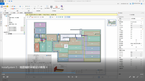
视频1 - 地面辐射采暖系统设计的各个典型阶段 [1]
视频2 - 建筑结构的准备[2]
视频3 - 设定项目的一般参数[3]
视频4 - 在平面图上进行项目的图形编辑[4]
视频5 - 计算和结果的分析[5]
视频6 - 绘制引线管路径、将分集水器和各供热供冷区连接起来[6]
视频7 - 系统参数的调整、优化热工和水力计算结果[7]
视频8 - 图形的修改和完善、计算书和图形的打印与输出[8]
项目文件
本课程所使用的项目文件:一独栋住宅地面和墙面辐射系统的设计(课程示例)。
初始状态
项目包含了模板中所定义的一套完整的省缺设置
房屋的结构是基于DWG格式的底图图纸。 更多信息见:项目案例表。
操作步骤
系统设计 - 湿式辐射系统
编辑一般参数和创建建筑结构
打开一新的项目文件
定义目录和一般参数
更多信息,见: 使用项目中的目录和目录数据.
在一般参数 中设定省缺参数:
- 楼层管理 - 添加所需要的楼层数。更多信息,见: 建筑结构的准备
- 目录 - 根据项目案例 表中的清单,选择如下的目录:
- 辐射系统
- 管材和管件
- 绝热
- 阀门及配件
- 供热/供冷系统计算 - 为下述内容给定参数:
- 水力分配系统
- 默认类型和参数
- 辐射系统
- 地面系统
- 墙面系统
- 分集水器、配件和控制
- 水力分配系统
建筑结构的准备
- 为每一楼层导入底图,并相应设置它们的绘图单位,然后通过插入参考点 标签,确定各层图纸上下的相对位置关系。更多信息,见: 导入底图文件
- 利用捕捉 模式,在设定了绘图单位的图纸上描出房间。更多信息,见: 手动创建建筑结构
- 使用房间编号 功能,从每层左上角的房间开始给房间自动编号。
- 在参数表 中修改如下的参数:
- 设计温度:卫浴间 24°C,大堂 16°C。
- 在供热 部分,通过选择适宜的房间类型设定允许的最高地表温度。
- 对于非采暖房间,将其热负荷指标设定为"0"。更多信息,见: 创建建筑结构
- 在3D视图 中核实所输入的建筑结构的正确性。更多信息,见: 检查所创建的建筑结构的正确性
编辑装置 - 湿式辐射系统
插入供热/供冷区
- 在选定的房间插入供热/供冷区 部件。
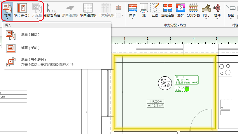
1. 插入 供热/供冷区 - 用分割/伸缩缝 工具修改供热/供冷区 和/或改变它们的形状使其覆盖想要的盘管区域(如绕开楼梯、浴缸等区域)。
- 按照相关的膨胀缝的设置原则,分割所选定的供热/供冷区 。

编辑供热/供冷区参数
- 选择装饰面层。
选中供热/供冷区 部件并在其参数表中选择表面装饰层 的类型。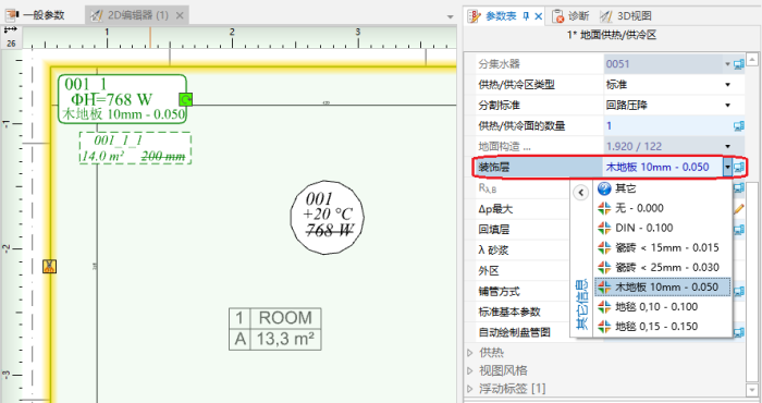
2. 表面装饰层 - 更改供热/供冷区 的类型。
- 点击被引线管覆盖较大面积的供热/供冷区 ,并在其 参数表 中,将其类型更改为由引线管供热/供冷 。 注意在这种情况下,将删除与分集水器的连接。
- 选中那些没有铺设盘管的供热/供冷区 并将其类型改为无管材。
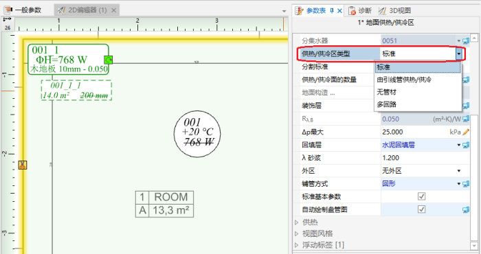
3. 类型 供热/供冷区
- 确定外区(根据DIN1264标准,外区指距外墙外窗最多1米宽的条形区域)。
指定并设置外区 。更多信息,见: 定义外区。


插入分/集水器
- 在每一楼层插入分/集水器。 分/集水器 可与分集水器箱一起插入图中。
更多信息,见: 分集水器和配件
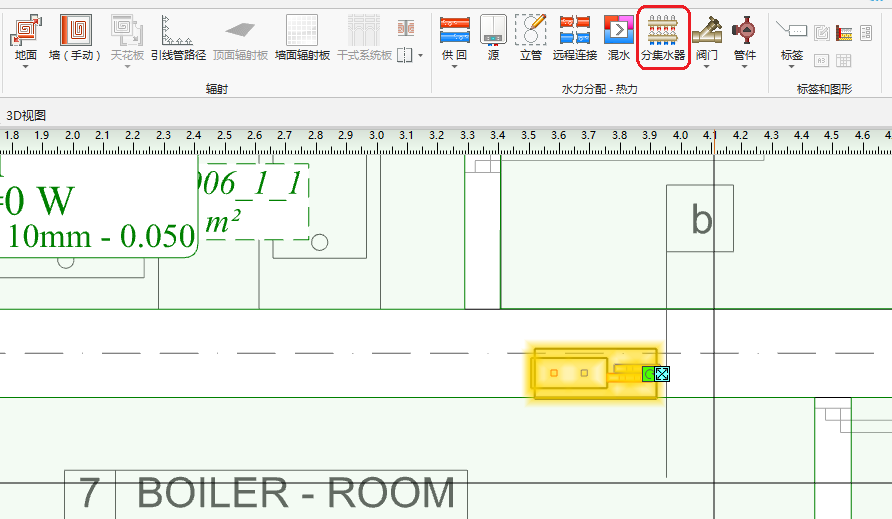
4. 插入 分/集水器

引线管路径
- 使用引线管路径 将分集水器与供热/供冷区连接。引线管路径 能够自动生成引线管。
更多信息,见: 编辑辐射系统中的引线管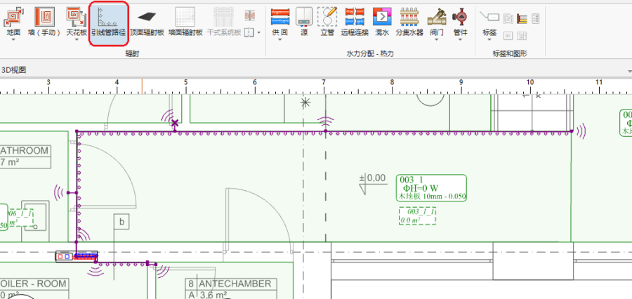
5. 绘制 引线管路径

系统编辑 - 连接分集水器
插入源
- 在最低的楼层插入源 。
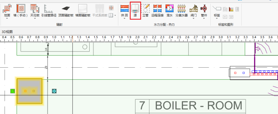
6. 插入 源

插入立管
- 插入立管,并给它指定一个符号,然后定义它的高程(从0层至1层)。
更多信息,见: 使用"立管"部件连接各楼层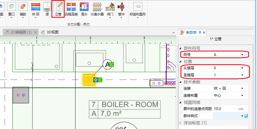
7. 安放 立管

水力分配
- 使用管路 部件,在捕捉 和定向线 模式下,通过绘制管网将源、分/集水器、立管 彼此连接在一起。
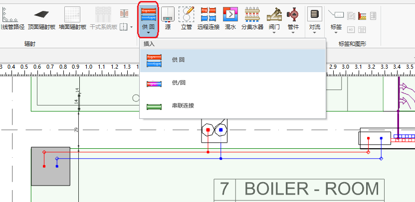
8. 连接系统部件

插入配件
- 在管路上布置阀门。
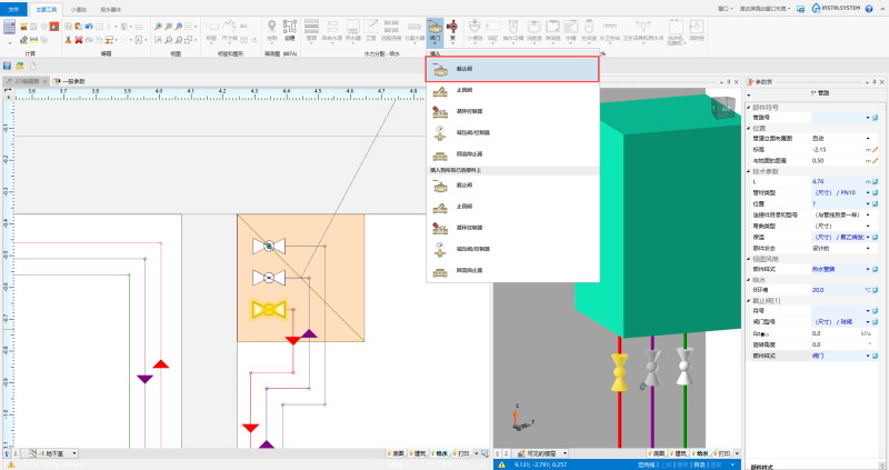
9. 插入 配件 - 在参数表 里选择阀门型号 。
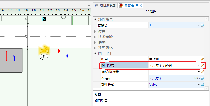
10. 阀门型号 - 使用复制 - 粘贴,在其它管路上安装同样类型的阀门。


核实系统安装的正确性
- 使用检查连接 功能(快捷键: Shift + F2)核实系统安装的正确性。
- 使用3D视图 核实系统安装的正确性及检查冲突。
更多信息,见: 核实系统安装的正确性
修改系统参数 - 手动修改(最佳化)
- 进入一般参数 窗口,在 供热/供冷系统计算/源 中,修改控制回路所使用的辐射系统的供水温度。
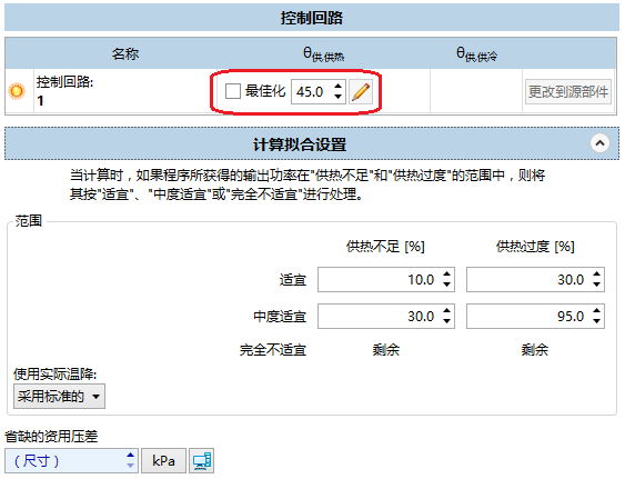
11. 控制回路 - 修改个别回路的管间距和温降。
更多信息,见: 辐射系统的交互式计算 - 修改供热地面/墙面的结构。
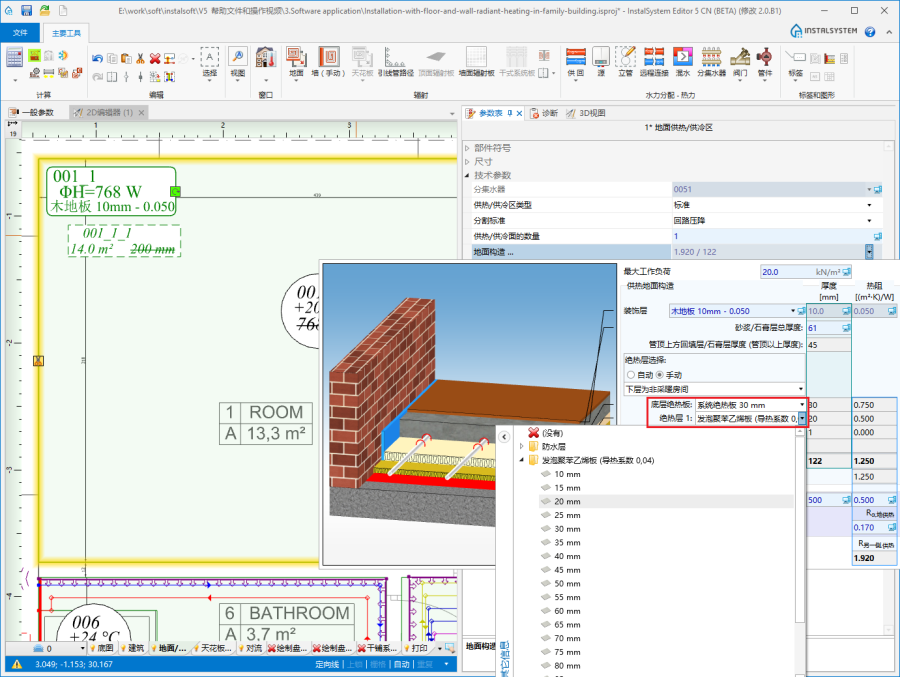
17. 地面构造 ... - 修改回路最大压降。
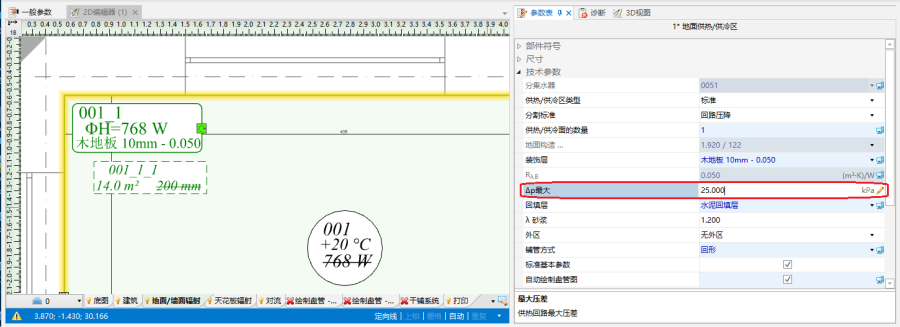
18. 回路最大压降


计算和诊断
- 点击计算 工具栏中的
 标签进行完整的计算。
 - 在窗口 列表中选择诊断 窗口或按F8打开诊断 窗口。
- 在交互式辐射系统计算 窗口中,对结果进行交互式检查。更多信息,见: 辐射系统的交互式计算。
- 在计算完整后,检查诊断 窗口中的信息,如果有错误显示,首先应修改错误。更多信息,见: 计算和诊断
要特别注意:- 热负荷或冷负荷的满足率。
- 自动生成的引线管路径的正确性。
- 相邻供热/供冷区构造层的高度/厚度是否有不希望的差异。

编辑系统装置及其参数
在此阶段,可以在以下范围内对系统装置及其参数进行手动修改:
修改将供热/供冷区 分割成供热/供冷面 的分割线
更多信息,见: 修改自动分割后的分割线
手动修改由引线管路径自动生成的引线管
更多信息,见: 引线管路径 - 手动修改由引线管路径自动生成的引线管
添加辐射系统盘管图
更多信息,见: 添加辐射系统盘管图
在计算过程中使用图形中的盘管长度
更多信息,见: 如何在计算中使用图纸中的回路长度?
再次计算和检查结果
- 检查计算结果,特别要注意:
- 房间热负荷的满足率。
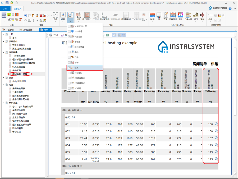
19. 所需供热输出的满足率 - 在供热/供冷地面 中所确定的构造层厚度,检查一下是否与周围区域有不必要的高度/厚度差异。
20. 地面构造 ... - 材料清单。
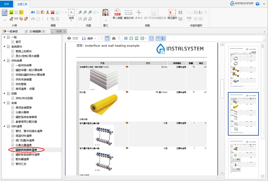
21. 材料清单 - 供暖 / 供冷 - 辐射供热部件清单
- 房间热负荷的满足率。


创建系统示意图
系统示意图可自动生成。更多信息,见: 自动创建系统示意图.

准备打印/输出图纸
标签
- 在部件上插入所需要的标签。
- 配置标签的外观。
更多信息,见: 部件外观和标签的设置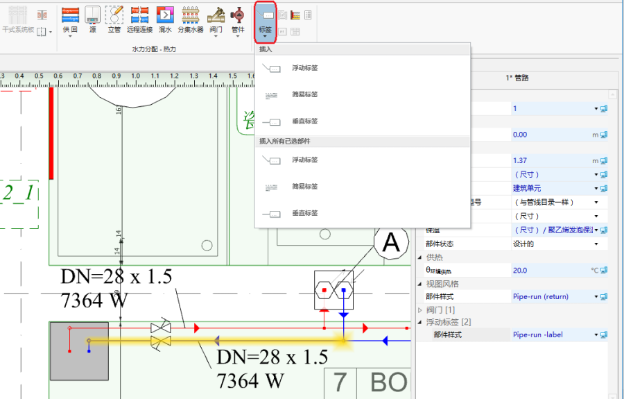
22. 插入 标签

分集水器设置表
- 插入分集水器设置表。
更多信息,见: 分集水器设置表的插入与设置
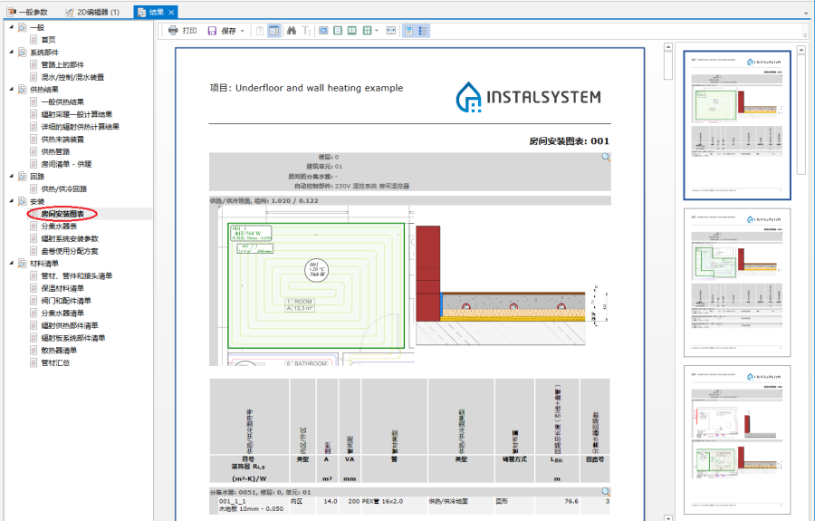
盘管辐射构造断面图
- 插入盘管辐射构造断面图,如有必要,可重置比例和配置。
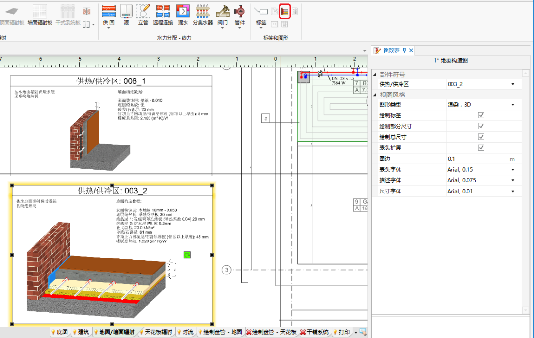
23. 盘管辐射构造断面图

辐射供暖供冷回路
图框
- 从标签和图形 工具栏中选择插入图框。
- 在参数表 中选择图框。
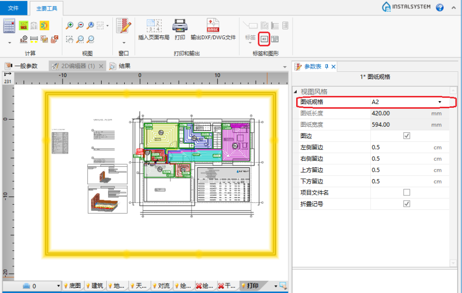
24. 插入 图框

标题栏
- 从标签和图形 工具栏中插入标题栏。
- 在参数表 中选择表格模板,有多种标题栏样式供选择。
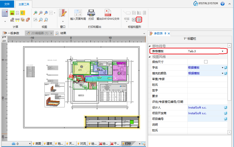
25.标题栏

打印/输出结果
- 打印/输出图纸。
- 打印/输出结果。
更多信息,见: 输出 / 打印结果和图纸
BIM - 将系统输出至IFC模型
进入打印编辑器,在主工具 选项卡,打印和输出 工具栏中,使用 IFC 文件输出 图标,指定所需的设置,然后执行系统装置的导出。

更多信息,见: BIM - 将项目的建筑和安装数据输出成IFC模型。
Editing an installation - dry radiant systems
The course of designing dry systems essentially follows that of the wet systems.
Additionally it is possible within a 供热/供冷区 type component to insert dry system plates and cut them to fit within room borders or to fit to the edges of other plates. The resulting quantities of plates are then included in the bill of materials. In addition, when routing the feeds and loops, it is necessary to take into account the arrangement of grooves in the dry system plates.
Editing general data and creating the building structure
Specify default data in 一般参数:
- On the 地面系统 tab, field 默认的系统/固定方式, select the dry system of the particular manufacturer.
- Other data in accordance with: Editing general data and creating the building structure.
Editing an installation - dry radiant systems
Inserting 供热/供冷区 components
- Insert 供热/供冷区 components in selected rooms. 更多信息,见: Heating/cooling zone.
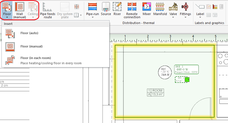
23. Inserting 供热/供冷区 - Cut out appropriate fragments of: 供热/供冷区 and/or change their shapes to adapt them to occupied areas (stairs, bathtubs) in rooms.
更多信息,见: Openings in heating-cooling areas zone.

Inserting dry system plates
- Add 干式系统板 components to the project. 更多信息,见: Inserting plates in dry floor heating system.
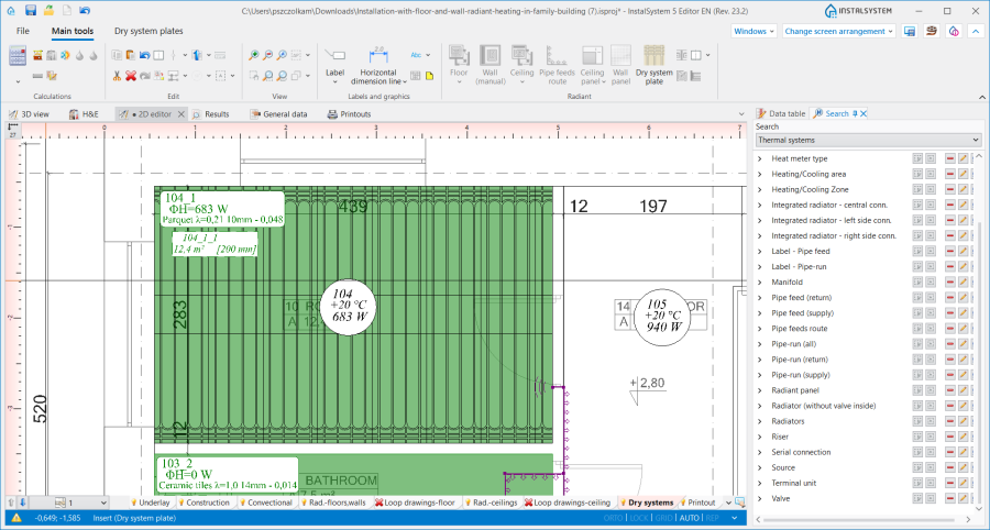
24. Inserting plates in dry floor heating systems.

Editing heating/cooling zone data
- Change of type for 供热/供冷区.
- Mark these 供热/供冷区 where significant surface area is occupied by pipe feeds and change their type to 由引线管供热/供冷. Remember in this case to remove connections with the manifold.
- Mark these 供热/供冷区 where no loops are to be arranged and change their type to 无管材.
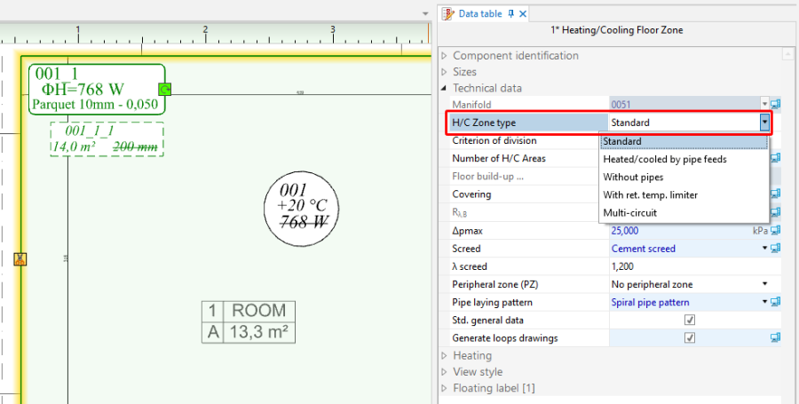
25. Type 供热/供冷区.

Inserting 分/集水器 components
- Insert 分/集水器 on every storey. 分/集水器 is inserted in the drawing together with manifold cabinet.
更多信息,见: Manifolds for radiant system and their accessories.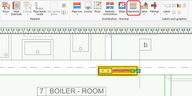
26. Inserting a 分/集水器.

Pipe feeds routing
- Connect 供热/供冷区 with manifolds using 引线管路径. 引线管路径 enables automatic generation of pipe feeds.
更多信息,见: Editing pipe feeds in a radiant system.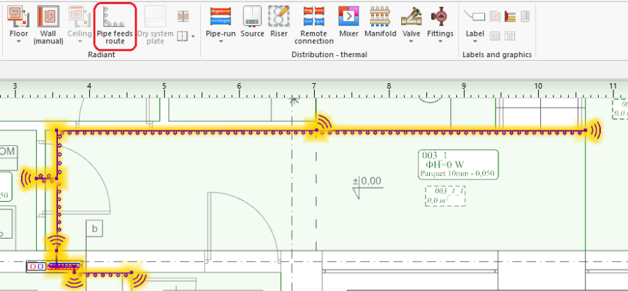
27. Inserting a 引线管路径.

Edit installation - feed to manifolds
Edit installation - feed to manifolds.
Verify correctness of installation structure
Verify correctness of installation structure.
Adjusting installation parameters - manual modifications (optional)
Adjusting installation parameters - manual modifications.
Calculations and diagnostics
Editing an installation and its parameters
更多信息,见: Editing an installation and its parameters.
Manual correction of automatically generated pipe feeds route
- After generating pipe feeds their arrangement in relation to the grooves in the 干式系统板 components should be verified and adjusted manually, if necessary.
更多信息,见: Pipe feeds route - manual correction of automatically generated pipe feeds route.
Appending drawings with radiant system loops
- After completing project calculations the arrangement of loops in relation to the grooves in the 干式系统板 components should be verified. 更多信息,见: Manual editing of loop drawings in dry systems with guide plates.
Recalculation and verification of results
更多信息,见: Recalculation and verification of results.
Generating schematic views
The schematic view will be generated automatically. 更多信息,见: Automatically generate schematic views.
Prepare drawing for printing/export
更多信息,见: Prepare drawing for printing/export.
Print/export results
更多信息,见: Print/export results.
BIM - Export of the installation to an IFC model
更多信息,见: BIM - Export of installation and construction data from the project to IFC models.


在干式地面辐射系统中使用干式系统板
更多信息,见: 在干式地面辐射系统中插入干式系统板