排水系统的设计
跳转到导航
跳转到搜索
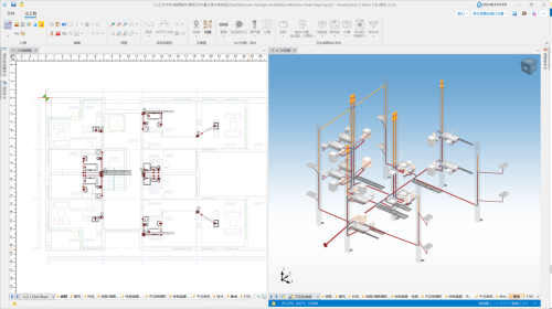
视频:排水系统设计教程
| 产品 | InstalSystem 5 |
| 文章类型 | 设计课程 |
| 版本的最新内容 | 2021-12-21 |
课程内容
本文介绍了建筑内部卫生设备和建筑物排污口之间的重力排水系统设计的基本方法。
模块和软件的配置
- InstalSystem 5 需带有如下模块:
- 室内重力排水系统
视频教程
欢迎观看我们的视频教程,视频中有对本文所述的功能进行讲解和介绍的内容
简介 [1]
1.操作界面的设置[2]
2.设定项目的一般参数[3]
3.1 图形编辑 - 生活排污口和立管[4]
3.2 图形编辑 - 固定装置[5]
3.3 图形编辑 - 复制装置到其他楼层[6]
4 计算和诊断报告的分析[7]
5 生成系统示意图[8]
6 计算结果的分析[9]
7 准备打印/输出图纸[10]
8.1 补充说明 - 通气管[11]
8.2 补充说明 - 旁路通风[12]
8.3 补充说明 - 支架、凹槽、安装隔板[13]
项目文件
本课程中使用的项目文件:多层住宅排水系统设计实例。
初始状态
项目包含有模板文件中设定的完整的缺省参数,建筑结构也已根据DWG布局做了详细说明。
设计步骤
打开项目文件
- 创建新项目的设计时,请从列表中选择包含排水系统省却参数的模板。
- (或): 打开现有建筑结构的文件 - 至少应包括正确的纵坐标和楼板厚度。如果设计文件是由不包括排水系统配置的软件包所创建的,请从相应模板中导入排水系统的一般参数。
更多信息,见: 模板文件
编辑项目的一般参数
选择 排水系统计算.
检查如下对排水系统几何形状有重大影响的参数,这些参数是每个项目独有的:
- 至外部管网的排水口的默认深度(相对于所设计的“正负零”标高)
- 各层楼板上地面层厚度的说明 - 注意!这可能会影响本文件中先前所做的其他系统或正在做的系统的设计。排水装置固定在地面上或距地面指定的高度处。
当打开没有排水模块和专用排水设计模板的软件包中所创建的文件时,可能需要进一步调整一般参数:
- 在排水系统计算 选项卡上指定:
- 计算标准和选项 :
- 在计算标准 选项卡上选择当地适宜的标准,
- 建筑类型 ,
- 根据设计要求和适用法规指定最小坡度,
- 为器具排水管的连接方向控制 指定省缺的方向,
- 对于选定的方向,定义排水横支管在立管上的连接点与地面完成面的距离 的默认值,该值将应用于项目中的所有楼层,然后可以在选定的楼层上单独修改,
- 省缺的管路充满度。
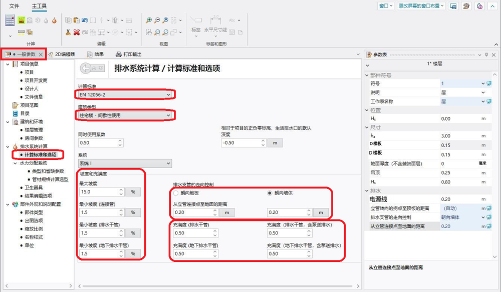
1.在计算标准和选项 中指定坡度和充满度
- 计算标准和选项 :

- 在水力分配系统 选项卡上,对于有关如下部件,指定 默认类型和参数:
- 对于各个管道位置的默认的管材类型: 排水 / 通气管,
- 管路连接的默认方式 - 取决于给定位置省缺管道目录的内容,
- 默认类型: 其它部件 。
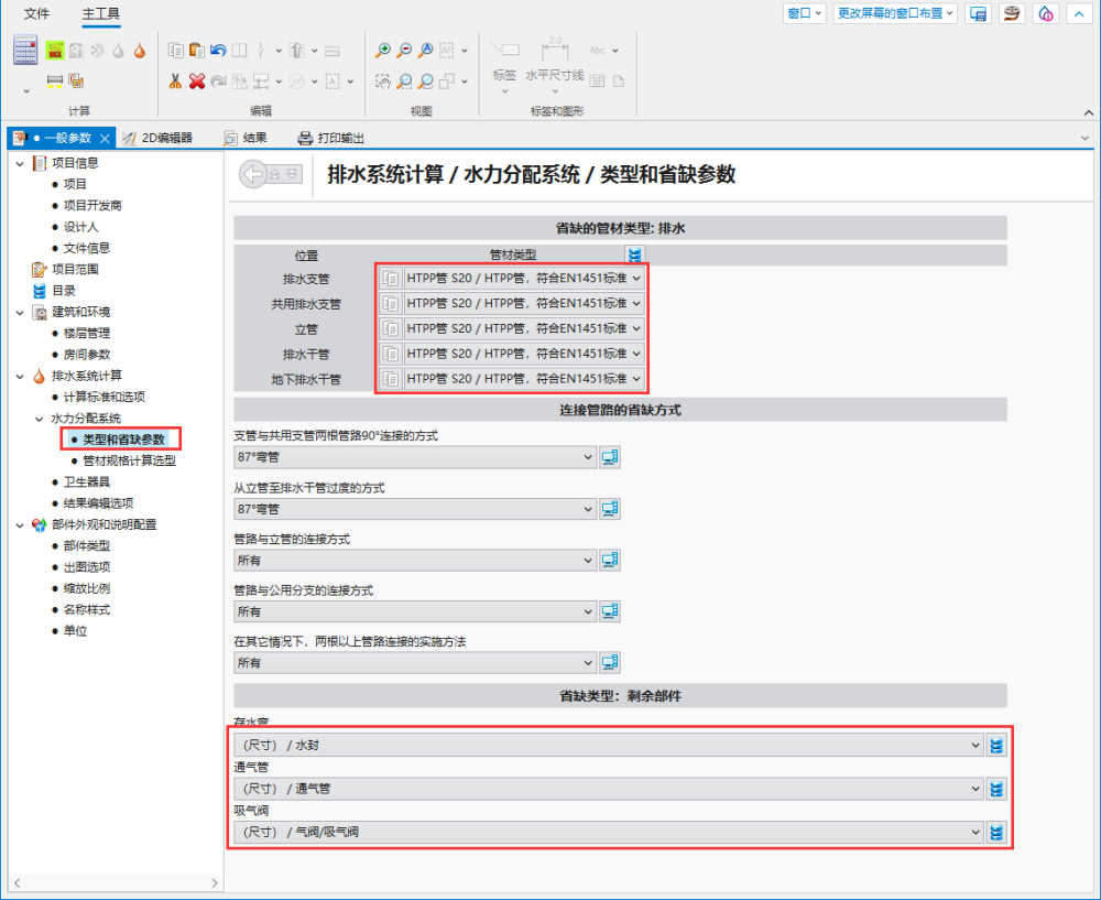
2.在默认类型和参数 选项卡中选择 默认的管材类型: 排水 / 通气管 并更改默认类型: 其它部件
- 在卫生器具 表格中,指定与如下有关的参数:
- 默认的连接系统 - 在为指定的管道连接下拉菜单中,为给定类型的卫生器具 选择适当的连接系统,
- 其它卫生器具的连接系统 - 为其余类型的卫生器具选择共同的连接系统。

3.在卫生器具 选项卡中指定默认支架, 默认的连接系统, 其它卫生器具的连接系统


- 在楼层管理 中,为项目设定一般参数
- 对于有排水管网的楼层,确定排水立管转成排水横管的拐点 所要求的值,“自动”意味着让程序根据污水口的位置来决定。也可手动指定一个值, 如我们可以将主下水道的位置设置在地下室天花板下。
- 器具排水管的连接方向控制 - 如果给定楼层上的值与上述一般参数中规定的值不同,则可进行更改,
- 排水横支管在立管上的连接点与地面完成面的距离 - 负值表示在楼板或天花板内的卫浴竖井中的立管上放置连接点,这可能是保持较低卫浴设备出水口的适当坡度所必需。
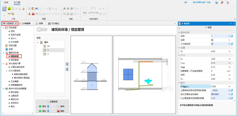
4.对于每层,均可修改排水横支管在立管上的连接点与地面完成面的距离

编辑系统和其参数
编辑系统的结构
- 插入卫生设备,如果这些设备未包含在文件中,例如来自先前完成的供水系统设计。更多信息,见:给水系统的设计,
- 定义立管 的位置和参数:楼层范围、末端通气管,
- 插入生活污水排出口 并确认其在模型中的位置,
- 使用管路 部件将卫浴设备与立管 连接。注意!在排水系统中,该部件始终由单个部分组成。
- 在生活污水排出口 所在的楼层上,将其与立管 连接,形成排水横管。除非已手动指定排水立管转成排水横管的拐点 值,否则省缺情况下,该排水横管的标高将被调节到生活污水排出口 的位置。
Editing the installation structure
- Insert sanitary appliances, if these were not included in the file, e.g. from a previously completed design of water supply system 更多信息,见: Editing sanitary installation.
- Insert 立管 elements and complete their essential data in the 参数表 window:
- Depending on the purpose of the 立管 element, declare the proper type in the 管材类型 field.
- In the 立管顶端的部件 field, defie the way in which the pipe-run at the last storey for the 立管 element finishes:
- For the waste stack, it is necessary to choose the vent element (e.g. 通气管), leaving the 无 option selected means that a vent manifold should be added in future,
- The vent 立管 should be ended with a vent element, or it should be connected to the drainage stack.
- In the 位置 section, declare the range of storeys of the element.
- Define additional parameters for double stacks (排水 + 通气管): 管道轴线距离, 自动生成平行通气管路 checkbox selection.
- For the立管 elements with bypass ventilation (with selected checkbox 自动生成平行通气管路 in the 参数表 element window), verify and, if needed, change the following parameters:
- Select the 创建每层中间的通气管连接 checkbox,
- Set the value in the 中间通气连接点与天花板的距离 field,
- Change the value in the 与排水立管连接的通气立管下端的标高 field,
- (Optional) declare a number > 0 in the 额外泄压立管占据的楼层数 field (counting from the lowest storey).
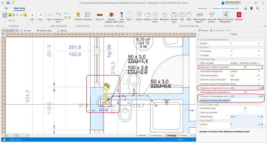
5. 自动生成平行通气管路.
- Insert the 生活污水排出口 and verify its position in the model,
- Connect the appliances with the 立管 using the 管路 components. ATTENTION! In the drainage system this component always consists of a single section. If, for perpendicular connections, other than 90-degree branch fittings are needed, they should be declared in the 一般参数 window in the 默认类型和参数 tab in the 管路连接的默认方式 section, and connections of 重力排水管 elements should be drawn as perpendicular (do not use "chamfering" in the plan view).
- On the storey where 生活污水排出口 is placed, connect it with the 立管, to form the collector sewer. The collector sewer elevation is by default adjusted to the posion of the 生活污水排出口, unless the value of 排水立管转成排水横管的拐点 has been specified manually.

确认安装结构的正确性
- 使用 检查连接 功能(快捷方式:Shift+F2)检查安装部件连接的正确性。注意!对于某些类型的设备,其接近方向应垂直于对象(例如,带尾部出口的马桶),此功能会自动在设备旁边创建短的管路,以确保此垂直度。
- 确认安装结构的正确性,并使用3D视图 检查与其他系统的碰撞。如果需要,启用其他编辑范围的视图,建议关闭墙的显示。
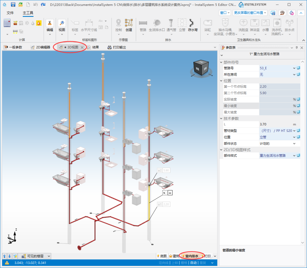
5. 使用3D视图 检查排水系统安装的正确性 - 临时检查一下模型中垂直的管路布置(计算时可能会有所改变)。
- 如有必要,请指定管路末端的标高(注意管路与其他部件连接时产生的约束)、管路的实际坡度。

注意在这些变更之后,必须再次检查
编辑安装部件的参数
- 检查并调节设备的排水特定参数(DU、出口直径)
- 如有必要,检查并调整省缺值以外的管路参数(管道类型、直径设置、位置)
计算
如果在检查过程中未发现错误,请单击计算 工具栏上的 ,开始排水系统计算 。
通过计算,最终确定管路的垂直布置。
检查结果
- 计算后,应通过3D视图检查系统的布置
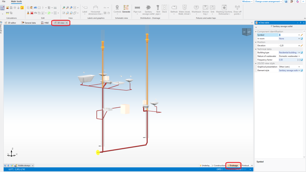
6. 使用3D视图 功能检查管路的布置 - 可在图纸上直接检查管材和管件所计算的直径
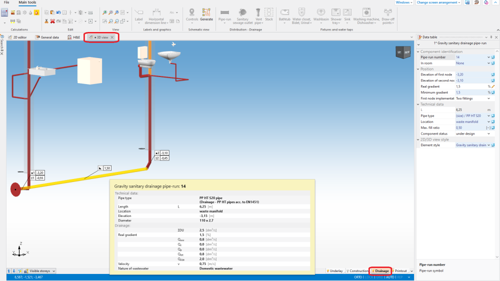
7. 使用管路特性窗口检查管路直径 - 计算结果的其他展示形式包括部件标签和计算书。更多信息,见:查看和打印计算结果
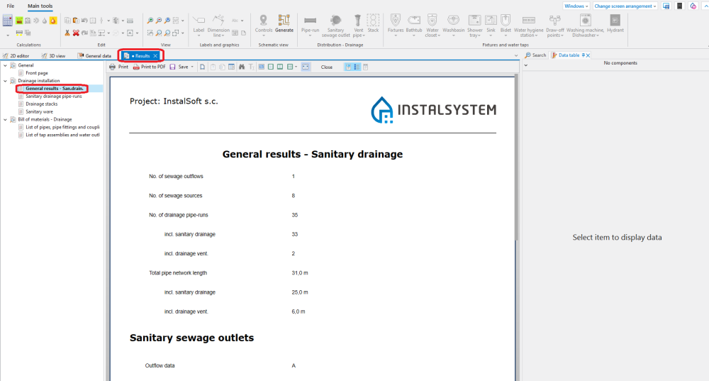
8. 一般结果 - 排水


创建系统示意图
示意图可自动生成,更多信息,见:自动创建系统示意图
图纸的输出/打印P
- 如果在打印输出中想包含管路的计算结果,则必须插入标签。更多信息,见: 准备导出/打印图纸
- 完成的图形可以打印和/或导出。更多信息,见: 导出/打印结果和图纸