在干式地面辐射系统中插入干式系统板:修订间差异
| 第26行: | 第26行: | ||
===Manual inserting plates in dry floor heating system=== | ===Manual inserting plates in dry floor heating system=== | ||
* ''' | * '''''<IS_TS id=KlocekDrySysName/>'' is inserted within the ''<IS_TS id=iNameOPStrefaPodlogGrzejnych/>'' area'''.<br/>{{Info}} [http://en.help.instalsoft.com/Heating/cooling_zone Heating/cooling zone ]<br/> Therefore this step has to be preceded by necessary design operations. {{Info}} [http://en.help.instalsoft.com/Design_of_radiant_heating_floor_and_wall_installation Design of radiant heating floor and wall installation] and selection in ''<IS_TS id=rsDanogi/>'' in the ''<IS_TS id=DaneInstalacjiPodlogowych/>'' section of "Dry system" in the ''<IS_TS id=strDomyslnySystemSposobMocowania/>'' field. <br> | ||
* ''' | * '''When inserting ''<IS_TS id=KlocekDrySysName/>'' appropriate catalog type should be selected in the ''<IS_TS id=DataEditorTable/>'' window''', to take into account the pipe spacing distance determined or specified for the zone. <br/> When the program configuration includes a dedicated toolbar it is possible to select an icon of a plate of defined type.<br/> | ||
* ''' | * ''' Inserting ''<IS_TS id=KlocekDrySysName/>'' components is supported by the ''<IS_TS id=strAUTOModeName/>'' mode''', both with regard to room outline, as well as to the plates themselves. {{Info}} [http://en.help.instalsoft.com/Inserting_plates_in_dry_floor_heating_system#Additional_information Additional information]<br/> | ||
* ''' | * ''' Using cut off pieces of ''<IS_TS id=KlocekDrySysName/>'' components. '''<br> The portion of ''<IS_TS id=KlocekDrySysName/>'' component being inserted that extends beyond ''<IS_TS id=iNameKonstrPomieszczenie/>'' or overlaps the ''<IS_TS id=KlocekDrySysName/>'' inserted before is automatically cut off. The cut off piece can be used in the project and the corresponding number of ''<IS_TS id=KlocekDrySysName/>'' components used is included in the bill of materials. The cut off pieces can be pasted outside of the drawing and reinserted elsewhere within the ''<IS_TS id=iNameOPStrefaPodlogGrzejnych/>'' cut to fit the edge provided that ''<IS_TS id=btWytnijDoSchowka/>'' and ''<IS_TS id=stractEditPasteCaption/>'' functions are used.<br/>{{#ev:youtube|im569TBm1Ek|900||||rel=0}} | ||
=== | === Adjusting the line dividing the ''<IS_TS id=iNameOPStrefaPodlogGrzejnych/>'' into ''<IS_TS id=iNameOPGrzejnik/>'' components=== | ||
* | * The lines dividing the ''<IS_TS id=iNameOPStrefaPodlogGrzejnych/>'' into ''<IS_TS id=iNameOPGrzejnik/>'' components determined automatically may not match the edges of ''<IS_TS id=KlocekDrySysName/>'' components inserted manually. In order to match these the dividing line has to be adjusted.<br/>{{Info}} [http://en.help.instalsoft.com/Heating/cooling_zone#Manual_indication_of_the_dividing_line Manual indication of the dividing line]<br/>{{Info}} [http://en.help.instalsoft.com/Heating/cooling_zone#Modifying_the_dividing_line_after_automatic_division Modifying the dividing line after automatic division]<br/>[[File:Dry-Systems-dividing-line.png|1100px|left|thumb|3. Adjustment of the dividing line]]<br clear="all"/> | ||
=== Inserting loop drawings === | |||
After proper arrangement of the dry system plates it is necessary to manually lay out the loops in accordance with {{Info}} [http://en.help.instalsoft.com/Appending_drawings_with_radiant_system_loops#Manual_editing_of_loop_drawings_in_dry_systems_with_guide_plates Manual editing of loop drawings in dry systems with guide plates]<br/> | |||
==Additional information== | ==Additional information== | ||
2018年1月6日 (六) 12:34的版本
Description
This functionality enables inserting 干式系统板 components to form a base for pipes in dry underfloor heating systems with guide plates.
干式系统板 components can be arranged in any configuration and cut to fit the edge of the room, while the cut away pieces can still be used.
After completing calculations a 辐射供热部件清单 is generated specifying the number of plates used in the project.

Location in the program
- Icon: 干式系统板 - available in the active scope of editing: 干式系统 (主工具 tab, 辐射 group)

- Additional dedicated tab with icons of plates with assigned types, depending on the configuration of the package.
Example of use
Manual inserting plates in dry floor heating system
- 干式系统板 is inserted within the 地面供热/供冷区 area.
更多信息,见: Heating/cooling zone
Therefore this step has to be preceded by necessary design operations. 更多信息,见: Design of radiant heating floor and wall installation and selection in 一般参数 in the 地面系统 section of "Dry system" in the 默认的系统/固定方式 field. - When inserting 干式系统板 appropriate catalog type should be selected in the 参数表 window, to take into account the pipe spacing distance determined or specified for the zone.
When the program configuration includes a dedicated toolbar it is possible to select an icon of a plate of defined type. - Inserting 干式系统板 components is supported by the 捕捉 mode, both with regard to room outline, as well as to the plates themselves. 更多信息,见: Additional information
- Using cut off pieces of 干式系统板 components.
The portion of 干式系统板 component being inserted that extends beyond 房间 or overlaps the 干式系统板 inserted before is automatically cut off. The cut off piece can be used in the project and the corresponding number of 干式系统板 components used is included in the bill of materials. The cut off pieces can be pasted outside of the drawing and reinserted elsewhere within the 地面供热/供冷区 cut to fit the edge provided that 剪切 and 粘贴 functions are used.
Adjusting the line dividing the 地面供热/供冷区 into 供热/供冷地面 components
- The lines dividing the 地面供热/供冷区 into 供热/供冷地面 components determined automatically may not match the edges of 干式系统板 components inserted manually. In order to match these the dividing line has to be adjusted.
更多信息,见: Manual indication of the dividing line
更多信息,见: Modifying the dividing line after automatic division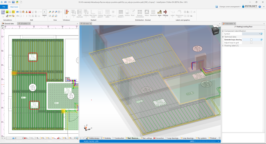
3. Adjustment of the dividing line

Inserting loop drawings
After proper arrangement of the dry system plates it is necessary to manually lay out the loops in accordance with 更多信息,见: Manual editing of loop drawings in dry systems with guide plates
Additional information
Podczas wstawiania oraz kopiowania/wklejania elementu 干式系统板 istnieje możliwość przełączania się pomiędzy aktywnymi krawędziami/punktami snapowania:
TAB - kursor przesuwa się zgodnie z ruchem wskazówek zegara
Shift+TAB - kursor przesuwa się przeciwnie do ruchu wskazówek zegara
- Jeżeli aktywna jest krawędź na wstawianym elemencie typu 干式系统板 (kursor jest na środku krawędzi) - program aktywuje 3 punkty: 1 na środku i 2 w narożnikach.
- Jeżeli aktywne są pojedyncze punkty na wstawianym elemencie typu 干式系统板 - program przełącza się pomiędzy brzegowymi punktami siatki elementu i snapuje do punktów siatki innych elementów typu 干式系统板.
- Kopiowanie kilku elementów typu 干式系统板 - program przełącza się sekwencyjnie pomiędzy punktami snapowania poszczególnych elementów typu 干式系统板 stanowiących kopiowany blok.
- Przesuwanie elementu typu 干式系统板 - aktywna krawędz lub punkt wybierany jest na podstawie miejsca "złapania" elementu i nie ma możliwości zmiany klawiszem "Tab"
.