建筑结构的准备:修订间差异
| 第27行: | 第27行: | ||
====<IS_TS id=rsPomieszczenie/> - 手工创建房间==== | ====<IS_TS id=rsPomieszczenie/> - 手工创建房间==== | ||
# 使用轮廓线手动创建一个''<IS_TS id=rsPomieszczenie/>''。<br/>{{#ev:youtube|XmWMZemLoVU|900||||rel=0}}<br/> | # 使用轮廓线手动创建一个''<IS_TS id=rsPomieszczenie/>''。<br/>{{#ev:youtube|XmWMZemLoVU|900||||rel=0}}<br/> | ||
或通过绘制对角线来创建房间。当用对角线创建房间时,''<IS_TS id=strORTOModeName/>'' 操作模式将会禁用。在绘制完对角线后,点击鼠标右键完成编辑。<br/>{{#ev:youtube|OEeIYuEQEmE|900||||rel=0}} <br clear="all"/> | |||
====<IS_TS id=rsPomieszczenie/> - identification within area bordered with drawn partitions==== | ====<IS_TS id=rsPomieszczenie/> - identification within area bordered with drawn partitions==== | ||
2017年2月5日 (日) 05:42的版本
描述
本文描述了如何为所设计的项目准备建筑结构和如何检查所创建的建筑结构的方法。本程序提供了多种准备建筑结构的方法,选择哪种方法取决于手头上所有的建筑结构和楼层平面图的数据源和所设计的范围。如果设计的范围不包括根据标准进行热负荷的计算,那么房间就可以在平面图中用没有冷围护结构的多边形的来表示。 每一楼层应单独使用一个平面图。
在程序中的位置
楼层管理
- 楼层管理 位于在一般参数 窗口中。
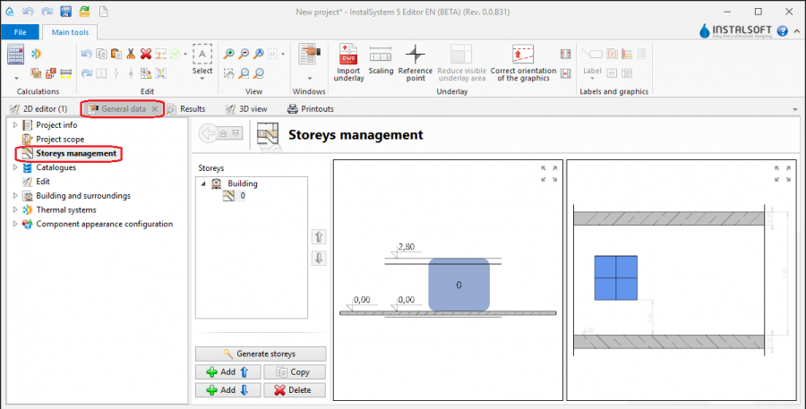
1. 楼层管理

导入底图
- 在2D编辑器 窗口中,当打开底图 编辑范围时,在主工具 的底图 工具栏中,可见与导入底图相关的部件和功能图标。

2. 导入底图

建筑结构
- * 在2D编辑器 窗口中,当打开建筑 编辑范围时,在主工具 的建筑 工具栏中,可见与导入建筑结构图相关的部件和功能图标。

3. 建筑结构部件

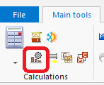
计算建筑结构
- 在主工具 的计算 中可见建筑结构计算。

4. 建筑结构计算

应用举例
自动创建建筑结构
多层建筑
- 创建所需要的楼层并附上相应的数据。本视频展示了某一两层楼的创建过程。
手动创建建筑结构
底图
底图是一个二维(平面)的图形对象,它来自外部的矢量文件。底图本身并不提供建筑结构部件,但可根据建筑的实际情况,手工创建。
更多信息,见: 导入文件
房间 - 手工创建房间
- 使用轮廓线手动创建一个房间。
或通过绘制对角线来创建房间。当用对角线创建房间时,定向线 操作模式将会禁用。在绘制完对角线后,点击鼠标右键完成编辑。
房间 - identification within area bordered with drawn partitions
- Place a series of 墙 components by entering at the start the thickness of the wall in 参数表 and moving the cursor along the internal edges of the walls on the underlay. In underlays retrieved from a DWG file make use of the snapping to indicated layer feature. After placing Internal walls insert External walls in similar manner.
- Place the following components: 窗, 门, 墙洞, 凹槽.
- Place the following components: 楼板. Outline of one storey is by default covered by a single slab.
- Place the following components: 屋顶.
- Carry out 建筑结构计算.
建筑结构计算 launches a number of operations associated with providing a complete building structure:
- cutting away partitions by the roof plane,
- automatic identification of rooms.
Manual editing of rooms and automatic identification of walls and slabs against the background of underlay
The operation of automatic identification of walls and slabs enables creating these partitions within spaces identified between rooms included in the project and the outline of the building.
To carry out the operation:
- In the project file with previously inserted rooms, make a building outline using the 'Building outline' function.
- Optionally: if the building outline is identical on a number of storeys, enter appropriate values in the fields 'from storey' and 'to storey' in the data table of the building outline component.
- Launch interpretation of external and internal walls and slabs based on rooms and building outline using the 自动生成墙、楼板和屋顶 function.
5.自动生成墙、楼板和屋顶

Importing a complete building structure
Importing a building structure from a BIM (gbXML) compatible format
更多信息,见: Import files
Importing a building structure from an InstalSystem 4 (ISB) project file
If necessary, manually correct or append the missing or incorrect components of the building structure thus obtained using the methods described above.
Verification of the correctness of building structure
Carry out the verification in the 3D视图 window