地面和墙面辐射供热系统的设计:修订间差异
跳转到导航
跳转到搜索
(→原始状态) |
(→原始状态) |
||
| 第7行: | 第7行: | ||
==原始状态== | ==原始状态== | ||
项目包含了模板中所定义的一套完整的省缺设置<br/>房屋的结构是基于DWG格式的底图图纸。 更多信息见:''项目案例表''。 | 项目包含了模板中所定义的一套完整的省缺设置<br/>房屋的结构是基于DWG格式的底图图纸。 更多信息见:''项目案例表''。 | ||
==Steps to perform== | |||
===Open new project file=== | |||
# Launch '''InstalSystem 5'''. | |||
# Open a new project and choose the preferred file version.<br/>{{Info}} [[Project and application management]] | |||
# Select the appropriate template.<br/>{{Info}} [[Software configuration#Template files|Template files]] | |||
===Define catalogues and general data=== | |||
Declare '''''<IS_TS id=rsDanogi/>''''' in default data: | |||
# ''<IS_TS id=StoreyManagement/>'' - add the required number of storeys<br/>{{Info}} [[Building structure#Preparing general data of building structure in project|Prepare building structure]] | |||
# ''<IS_TS id=strDlgKatalogiObslugaKatalogowHint/>'' - choose catalogues according to the list in the ''Project table'' with regard to: | |||
#* ''<IS_TS id=SystemyPlaszczyznowe/>'' | |||
#* ''<IS_TS id=KTRNazwaRodzaju/>'' | |||
#* ''<IS_TS id=KTINazwaRodzaju/>'' | |||
#* ''<IS_TS id=KTZNazwaRodzaju/>'' | |||
# ''<IS_TS id=InstalacjeCieplne/>'' - append information for: | |||
#* ''<IS_TS id=InstalacjaRozprowadzajaca/>'' | |||
#** ''<IS_TS id=DaneInstalacjiRozprowadzajacejCzynnikGrzewczyChlodniczy/>'' | |||
#* ''<IS_TS id=SystemyPlaszczyznowe/>'' | |||
#** ''<IS_TS id=DaneInstalacjiPodlogowych/>'' | |||
#** ''<IS_TS id=DaneInstalacjiSciennych/>'' | |||
#** ''<IS_TS id=RozdzielaczeSystemowPlaszczyznowychIAutomatyka/>'' | |||
{{Info}} [[Introduction to the work with the package InstalSystem 5#General data|General data]] | |||
{{Project table | |||
|is1 = <!-- Jest plik -> "|initial_state1= <link do pliku na ftp>" / Brak pliku -> "|is1=" --> | |||
|initial_file_name1 = <!-- Jest plik -> "|initial_file_name1= <tytuł pliku>, <rozszerzenie>" / Brak pliku -> "|initial_file_name1=" --> | |||
|is2 = <!-- Jest plik -> "|initial_state2= <link do pliku na ftp>" / Brak pliku -> "|is2=" --> | |||
|initial_file_name2 = <!-- Jest plik -> "|initial_file_name2= <tytuł pliku>, <rozszerzenie>" / Brak pliku -> "|initial_file_name2=" --> | |||
|final_state1 =http://download.instalsoft.com/public/helpsystem/SUZ/SUZ-RH-Design-of-radiant-heating-installation-v5/Installation-with-floor-and-wall-radiant-heating-in-family-building.isproj | |||
|final_state_name1 = Floor and wall radiant heating system in single-family house, isproj | |||
|fs2 = <!-- Jest plik -> "|final_state2= <link do pliku na ftp>" / Brak pliku -> "|fs2=" --> | |||
|final_state_name2 = <!-- Jest plik -> "|final_file_name2= <tytuł pliku>, <rozszerzenie>" / Brak pliku -> "|final_file_name2="--> | |||
|commercial_product =InstalSystem 5 | |||
|rev = Beta 30 | |||
|module1=InstalSystem basis | |||
|module2 =Heating system 5 | |||
|module3 =Radiant loop systems 5 | |||
|m4 = <!-- Jest moduł -> "|module4= <nazwa modułu z W6936>" / Brak kolejnego modułu -> "|m4=" --> | |||
|range =Radiant heating | |||
|catalogue1=Basic radiant systems | |||
|catalogue2=Brass and steel pipe couplings and fittings | |||
|catalogue3=Copper pipes and fittings EN 1057 | |||
|catalogue4=Standard mixers, pump and bypass units | |||
|catalogue5=Standard insulation catalogue | |||
|catalogue6=Neutral valves catalogue - typical construction | |||
|c7 = <!-- Jest katalog -> "|catalogue7= <nazwa katalogu>" / Brak katalogu -> "|c7=" --> | |||
|c8 = <!-- Jest katalog -> "|catalogue8= <nazwa katalogu>" / Brak katalogu -> "|c8=" --> | |||
|c9 = <!-- Jest katalog -> "|catalogue9= <nazwa katalogu>" / Brak katalogu -> "|c9=" --> | |||
|c10 = <!-- Jest katalog -> "|catalogue10= <nazwa katalogu>" / Brak katalogu -> "|c10=" --> | |||
|type =single-family | |||
|basement =no basement | |||
|number_of_storeys =2-storey | |||
|building_structure1 =http://download.instalsoft.com/public/helpsystem/SUZ/SUZ-RH-Design-of-radiant-heating-installation-v5/Base-ground-floor.dwg | |||
|file_name1 = Base drawing ground floor, dwg | |||
|building_structure2 =http://download.instalsoft.com/public/helpsystem/SUZ/SUZ-RH-Design-of-radiant-heating-installation-v5/Base-first-floor.dwg | |||
|file_name2 =Base drawing first floor, dwg | |||
|bs3 = <!-- Jest plik -> "building_structure3= <link do pliku na ftp>" / Brak pliku -> "|bs3=" --> | |||
|file_name3 = <!-- Jest plik -> "|file_name3= <tytuł rysunku, rozszerzenie>" / Brak pliku -> "|file_name3=" --> | |||
|bs4 = <!-- Jest plik -> "building_structure4= <link do pliku na ftp>" / Brak pliku -> "|bs4=" --> | |||
|file_name4 = <!-- Jest plik -> "|file_name4= <tytuł rysunku, rozszerzenie>" / Brak pliku -> "|file_name4=" --> | |||
|drawings_range =Plan view | |||
|logo =File:Logo-instalsoft-new.png | |||
|www =http://instalsoft.com www.instalsoft.com | |||
|legal_disclaimer =Copying of entire project and of its fragments allowed | |||
|calculation_results1 =http://download.instalsoft.com/public/helpsystem/SUZ/SUZ-RH-Design-of-radiant-heating-installation-v5/Floor-and-wall-heating-full-printout.xlsx | |||
|results_title1 =Full printout, xls | |||
|calculation_results2 =http://download.instalsoft.com/public/helpsystem/SUZ/SUZ-RH-Design-of-radiant-heating-installation-v5/Floor-and-wall-heating-full-printout.pdf | |||
|results_title2 =Full printout, pdf | |||
|calculation_results3 =http://download.instalsoft.com/public/helpsystem/SUZ/SUZ-RH-Design-of-radiant-heating-installation-v5/Floor-and-wall-heating-general-heating-results.pdf | |||
|results_title3 =Radiant heating calculation results, pdf | |||
|calculation_results4 =http://download.instalsoft.com/public/helpsystem/SUZ/SUZ-RH-Design-of-radiant-heating-installation-v5/Floor-and-wall-heating-bill-components.pdf | |||
|results_title4 =Bill of materials, pdf | |||
|calculation_results5 =http://download.instalsoft.com/public/helpsystem/SUZ/SUZ-RH-Design-of-radiant-heating-installation-v5/Floor-and-wall-heating-installation-parameters.pdf | |||
|results_title5 =Installation parameters, pdf | |||
|drawing_result1 =http://download.instalsoft.com/public/helpsystem/SUZ/SUZ-RH-Design-of-radiant-heating-installation-v5/Installation-with-floor-and-wall-heating-in-single-family-building-ground-floor.dwg | |||
|drawing_title1 = Ground floor, dwg | |||
|drawing_result2 =http://download.instalsoft.com/public/helpsystem/SUZ/SUZ-RH-Design-of-radiant-heating-installation-v5/Installation-with-floor-and-wall-heating-in-single-family-building-first-floor.dwg | |||
|drawing_title2 = First floor, dwg | |||
|drawing_result3 =http://download.instalsoft.com/public/helpsystem/SUZ/SUZ-RH-Design-of-radiant-heating-installation-v5/Floor-and-wall-heating-ground-floor-print.pdf | |||
|drawing_title3 = Ground floor, pdf | |||
|drawing_result4 =http://download.instalsoft.com/public/helpsystem/SUZ/SUZ-RH-Design-of-radiant-heating-installation-v5/Floor-and-wall-heating-first-floor-print.pdf | |||
|drawing_title4 = First floor, pdf | |||
|dr5 = <!-- Jest plik -> "|drawing_result5= <Link do pliku na ftp>" / Brak pliku -> "|dr5=" --> | |||
|drawing_title5 = <!-- Jest plik -> "|drawing_title5= <tytuł rysunku, rozszerzenie>" / Brak pliku -> "|drawing_title4=" --> | |||
|dr6 = <!-- Jest plik -> "|drawing_result6= <Link do pliku na ftp>" / Brak pliku -> "|dr6=" --> | |||
|drawing_title6 = <!-- Jest plik -> "|drawing_title6= <tytuł rysunku, rozszerzenie>" / Brak pliku -> "|drawing_title4=" --> | |||
}} | |||
===Prepare building structure=== | |||
# Import, rescale and arrange in relation to each other, by inserting ''<IS_TS id=iNameReferencePoint/>'', base drawings for each storey.<br/>{{Info}} [[Import files]] | |||
# Redraw rooms in the rescaled base drawing using the ''<IS_TS id=strAUTOModeName/>'' mode.<br/>{{Info}} [[Building structure#Manual editing of rooms in imported base drawing|Insert rooms]] | |||
# Automatically number the rooms using the ''<IS_TS id=btNumerujPomieszczenia/>'' function. Start from the room in the upper left corner of each storey. | |||
# Make appropriate corrections in ''<IS_TS id=DataEditorTable/>'': | |||
#* Design temperature: enter 24°C for bathrooms, 16°C for lobby. | |||
#* Maximum permissible floor surface temperature by selecting appropriate room type in the ''<IS_TS id=strOgrzewaniePlaszczyznowe/>'' section. | |||
#* For unheated rooms, specify the value of heat loss index as "0".<br/>{{Info}} [[Introduction to the work with the package InstalSystem 5#Setting up the building structure|Setting up the building structure]] | |||
# Verify the correctness of the structure entered in ''<IS_TS id=View3D/>''.<br/>{{Info}} [[Introduction to the work with the package InstalSystem 5#Verification of the correctness of building structure|Verification of the correctness of building structure]] | |||
===Edit installation - radiant system=== | |||
====<IS_TS id=iNameOPStrefaPowGrzejnych/>==== | |||
# Insert ''<IS_TS id=iNameOPStrefaPowGrzejnych/>'' components in selected rooms.<br/>[[File:Suz-rh-ribbon-spgch.png|900 px|thumb|left|1. Inserting ''<IS_TS id=iNameOPStrefaPowGrzejnych/>'']]<br clear="all"/> | |||
# Cut out appropriate fragments of: ''<IS_TS id=iNameOPStrefaPowGrzejnych/>'' and/or change their shapes to adapt them to occupied areas (stairs, bathtubs) in rooms. | |||
# Divide selected areas of ''<IS_TS id=iNameOPStrefaPowGrzejnych/>'' with regard to required expansion allowances. | |||
# Declare and set up the ''<IS_TS id=strStrefaBrzegowa/>''.<br/>{{Info}} [[Heating/cooling areas zone#Peripheral zones of heating/cooling areas zone|Peripheral zones of heating/cooling areas zone]] | |||
====<IS_TS id=iNameRozdzielaczPure/>==== | |||
# Insert ''<IS_TS id=iNameRozdzielaczPure/>'' on every storey. ''<IS_TS id=iNameRozdzielaczPure/>'' is inserted in the drawing together with manifold cabinet.<br/>{{Info}} [[Manifold and accessories]] | |||
[[File:Rh-ribbon-manifold.png|900 px|thumb|left|2. Inserting ''<IS_TS id=iNameRozdzielaczPure/>'']]<br clear="all"/> | |||
====<IS_TS id=rpStrefaPrzylaczy/>==== | |||
# Connect ''<IS_TS id=iNameOPStrefaPowGrzejnych/>'' with manifolds using ''<IS_TS id=rpStrefaPrzylaczy/>''. ''<IS_TS id=rpStrefaPrzylaczy/>'' enables automatic generation of pipe feeds.<br/>{{Info}} [[Editing pipe feeds in a radiant system]] | |||
[[File:Rh-ribbon-pipe-feeds-route.png|900 px|thumb|left|3. Inserting ''<IS_TS id=rpStrefaPrzylaczy/>'']]<br clear="all"/> | |||
===Edit installation - feed to manifolds=== | |||
====<IS_TS id=iNameCOZrodlo/>==== | |||
# Insert ''<IS_TS id=iNameCOZrodlo/>'' on the lowermost storey.<br/>[[File:Rh-ribbon-source.png|900 px|thumb|left|4. Inserting ''<IS_TS id=iNameCOZrodlo/>'']]<br clear="all"/> | |||
====<IS_TS id=iNamePion/>==== | |||
# Insert ''<IS_TS id=iNamePion/>'', assign a symbol to it and define its extent (from storey 0 to storey 1).<br/>{{Info}} [[Connecting storeys with the "Stack" element]]<br/>[[File:Rh-ribbon-riser.png|900 px|thumb|left|5. Inserting ''<IS_TS id=iNamePion/>'']]<br clear="all"/> | |||
====Distribution==== | |||
# Connect ''<IS_TS id=iNameCOZrodlo/>'', ''<IS_TS id=iNameRozdzielaczPure/>'', ''<IS_TS id=iNamePion/>'' with each other by drawing the network using the ''<IS_TS id=iNameDzialka/>'' component and the ''<IS_TS id=strAUTOModeName/>'' and ''<IS_TS id=strORTOModeName/>'' modes.<br/>[[File:Rh-ribbon-pipe-run4.png|900 px|thumb|left|6. Connecting system components]]<br clear="all"/> | |||
====Fittings==== | |||
# Insert ''<IS_TS id=pinNameZawor/>'' onto pipe-runs.<br/>[[File:Rh-ribbon-valve4.png|1000 px|thumb|left|7. Inserting ''Fittings'']]<br clear="all"/> | |||
# Select ''<IS_TS id=typZaworu/>'' in ''<IS_TS id=DataEditorTable/>''.<br/>[[File:Suz-rh-valve-data-table.png|900 px|thumb|left|8. ''<IS_TS id=typZaworu/>'']]<br clear="all"/> | |||
# Use Copy - Paste to insert fittings of the same type onto other pipe-runs. | |||
===Verify correctness of installation structure=== | |||
# Verify the correctness of the installation structure using the ''<IS_TS id=btCheckFlow/>'' function (Key shortcut: Shift + F2). | |||
# Verify the correctness of the installation structure and find conflicts using ''<IS_TS id=View3D/>''.<br/>{{Info}} [[Introduction to the work with the package InstalSystem 5#Verification of the correctness of installation structure|Verification of the correctness of installation structure]] | |||
===Edit installation components data=== | |||
====<IS_TS id=strOkladzinaWierzchnia/>==== | |||
# Mark selected ''<IS_TS id=iNameOPStrefaPowGrzejnych/>'' components and specify the type of ''<IS_TS id=strOkladzinaWierzchnia/>''.<br/>[[File:Suz-rh-covering-data-table1.png|700 px|thumb|left|9. ''<IS_TS id=strOkladzinaWierzchnia/>'']] | |||
====<IS_TS id=iNameOPStrefaPowGrzejnych/>==== | |||
# Mark these ''<IS_TS id=iNameOPStrefaPowGrzejnych/>s'' where significant surface area is occupied by pipe feeds and change their type to ''<IS_TS id=vltpgOgrzewanaPrzylaczami/>''. Remember in this case to remove connections with the manifold. | |||
# Mark these ''<IS_TS id=iNameOPStrefaPowGrzejnych/>s'' where no loops are to be arranged and change their type to ''<IS_TS id=vltpgSlepaBezRur/>''.<br/>[[File:Suz-rh-spgch-type-data-table1.PNG|700 px|thumb|left|10. Type ''<IS_TS id=iNameOPStrefaPowGrzejnych/>'']]<br clear="all"/> | |||
===Calculations and diagnostics=== | |||
====Radiant system calculations==== | |||
# Launch complete calculations by clicking the [[File:Calculator.png|35 px]] icon in the ''<IS_TS id=sObliczenie/>'' section of the toolbar. | |||
# Open the ''<IS_TS id=ErrorModuleTitle/>'' window by selecting it in the list of windows or by pressing F8. | |||
# After calculations are completed verify the messages listed in the ''<IS_TS id=ErrorModuleTitle/>'' window. If error messages are displayed, these must be eliminated in the first place. | |||
{{Info}} [[Introduction to the work with the package InstalSystem 5#Calculations and diagnostics|Calculations and diagnostics]] | |||
====Modifying system parameters to adapt attained output to required output==== | |||
# Change feed temperature of the radiant system.<br/>[[File:TB-control-circuit-settings-location.PNG|900 px|thumb|left|11. ''<IS_TS id=SettingsObwodyRegulacji/>'']]<br clear="all"/>[[File:Hs-suz-rh-control-circuit-ribbon.png|900 px|thumb|left|12. ''<IS_TS id=SettingsObwodyRegulacji/>'']]<br clear="all"/> | |||
# Change pipe spacing and temperature drop in individual loops.<br/>[[File:TB-interactive-radiant-calc-location.png|900 px|thumb|left|13. ''<IS_TS id=ShowInteractiveCalculationWindow/>'']]<br clear="all"/>[[File:Suz-rh-interactive-calc1.PNG|900 px|thumb|left|14. ''<IS_TS id=ShowInteractiveCalculationWindow/>'']]<br clear="all"/> | |||
# Change structure of heating floor\wall.<br/>[[File:Suz-rh-edytor-konstrukcji.PNG|900 px|thumb|left|15. ''<IS_TS id=strpnPGKonstrukcjaPodlogi/>'']]<br clear="all"/> | |||
# Change ''<IS_TS id=strLblMaxDPCaption/>''.<br/>[[File:Suz-rh-dp-max-loop-dem.PNG|900 px|thumb|left|16. ''<IS_TS id=strLblMaxDPCaption/>'']]<br clear="all"/> | |||
====Recalculation and verification of results==== | |||
# Verify calculation results paying special attention to: | |||
#* coverage of heat demand in rooms,<br/>[[File:Suz-rh-calc-results.png|900 px|thumb|left|17. ''<IS_TS id=RoomsListHeatPokrycieStratyCieplaPomieszczeniaFullHeader/>'']]<br clear="all"/> | |||
#* sized layers in ''<IS_TS id=iNameOPGrzejnik/>'', to see if there are no undesirable differences in height/thickness in adjacent areas.<br/>[[File:Suz-rh-hz-construction.png|900 px|thumb|left|18. ''<IS_TS id=strpnPGKonstrukcjaPodlogi/>'']]<br clear="all"/> | |||
#* bills of materials.<br/>[[File:Suz-rh-bill.PNG|900 px|thumb|left|19. ''<IS_TS id=ZestawienieMaterialowTherm/>'' - ''<IS_TS id=sZestawienieElementowOP/>'']]<br clear="all"/> | |||
===Prepare drawing for printing/export=== | |||
====<IS_TS id=Label/>==== | |||
# Insert required labels onto components. | |||
# Configure the label appearance (opc).<br/>{{Info}} [[Introduction to the work with the package InstalSystem 5#General data|Item 5. Component appearance configuration and editing parameters configuration]]<br/>[[File:Rh-ribbon-label.png|900 px|thumb|left|20. Inserting ''<IS_TS id=Label/>'']]<br clear="all"/> | |||
====<IS_TS id=iNameTabelkaRozdzielacza/>==== | |||
# Insert ''<IS_TS id=iNameTabelkaRozdzielacza/>''.<br/>{{Info}} [[Manifold and accessories#Manifold label and table|Manifold label and table]] | |||
====<IS_TS id=RysunekPrzekrojuKonstrukcji/>==== | |||
# Insert ''<IS_TS id=RysunekPrzekrojuKonstrukcji/>''. Rescale and configure, if necessary.<br/>[[File:Rh-structure-section-drawing4.png|1100 px|thumb|left|21. ''<IS_TS id=RysunekPrzekrojuKonstrukcji/>'']]<br clear="all"/> | |||
====<IS_TS id=WezownicaCaption/>==== | |||
# Automatically generate the ''<IS_TS id=WezownicaCaption/>'' drawings.<br/>{{Info}} [[Appending drawings with radiant system loops#Automatic generation of loop drawings|Automatic generation of loop drawings]] | |||
# Check the generated ''<IS_TS id=WezownicaCaption/>'' drawings and modify them manually, if necessary.<br/>{{Info}} [[Appending drawings with radiant system loops#Manual editing of loop drawings|Manual editing of loop drawings]] | |||
====<IS_TS id=iNameRamkaRysunkowa/>==== | |||
# Insert ''<IS_TS id=iNameRamkaRysunkowa/>''. | |||
# Select ''<IS_TS id=iNameRamkaRysunkowa/>'' in ''<IS_TS id=DataEditorTable/>'' .<br/>[[File:Rh-ribbon-paper-format.png|900 px|thumb|left|22. Inserting ''<IS_TS id=iNameRamkaRysunkowa/>'']]<br clear="all"/> | |||
====<IS_TS id=iNameTabelkaProjektu/>==== | |||
# Insert ''<IS_TS id=iNameTabelkaProjektu/>''. | |||
# Enter the required data in ''<IS_TS id=DataEditorTable/>''.<br/>[[File:Rh-ribbon-drawing-chart.png|900 px|thumb|left|23.''<IS_TS id=iNameTabelkaProjektu/>'']]<br clear="all"/> | |||
===Print/export results=== | |||
# Print/export drawings. | |||
# Print/export tables.<br/>{{Info}} [[Export / print results and drawings]] | |||
<!--Lista kategorii produktów handlowych, których artykuł dotyczy--> | |||
[[pl:projektowanie instalacji ogrzewania podłogowego i ściennego]] | |||
[[Category:InstalSystem 5]] | |||
[[Category:SOFTWARE APPLICATION]] | |||
2017年1月16日 (一) 10:09的版本
课程的内容
本文介绍了(干式和湿式)盘管辐射供热系统的设计计算方法。
所展示的案例是基于对一个2层无地下室的单户住宅而进行的设计。
模块和程序的配置
InstalSystem 5 包括下面的模块:
- 盘管辐射供热系统。
原始状态
项目包含了模板中所定义的一套完整的省缺设置
房屋的结构是基于DWG格式的底图图纸。 更多信息见:项目案例表。
Steps to perform
Open new project file
- Launch InstalSystem 5.
- Open a new project and choose the preferred file version.
更多信息,见: Project and application management - Select the appropriate template.
更多信息,见: Template files
Define catalogues and general data
Declare 一般参数 in default data:
- 楼层管理 - add the required number of storeys
更多信息,见: Prepare building structure - 目录 - choose catalogues according to the list in the Project table with regard to:
- 辐射系统
- 管材和管件
- 绝热
- 阀门及配件
- 供热/供冷系统计算 - append information for:
- 水力分配系统
- 默认类型和参数
- 辐射系统
- 地面系统
- 墙面系统
- 分集水器、配件和控制
- 水力分配系统
更多信息,见: General data
| 项目文件
|
Floor and wall radiant heating system in single-family house, isproj |
| 设计时使用 | InstalSystem 5 Rev. Beta 30 |
| 所需模块 | InstalSystem basis Heating system 5 Radiant loop systems 5 |
| 项目范围 | Radiant heating |
| 所用的产品目录 |
Basic radiant systems |
| 建筑类型 | single-family no basement 2-storey |
| 建筑结构 | Base drawing ground floor, dwg Base drawing first floor, dwg |
| 图纸范围 | Plan view |
| 设计者 |  www.instalsoft.com |
| 法律免责声明 | Copying of entire project and of its fragments allowed |
| 计算结果 | Full printout, xls Full printout, pdf Radiant heating calculation results, pdf Bill of materials, pdf Installation parameters, pdf |
| 设计图纸 | Ground floor, dwg First floor, dwg Ground floor, pdf First floor, pdf |
Prepare building structure
- Import, rescale and arrange in relation to each other, by inserting 参考点, base drawings for each storey.
更多信息,见: Import files - Redraw rooms in the rescaled base drawing using the 捕捉 mode.
更多信息,见: Insert rooms - Automatically number the rooms using the 房间编号 function. Start from the room in the upper left corner of each storey.
- Make appropriate corrections in 参数表:
- Design temperature: enter 24°C for bathrooms, 16°C for lobby.
- Maximum permissible floor surface temperature by selecting appropriate room type in the 供热 section.
- For unheated rooms, specify the value of heat loss index as "0".
更多信息,见: Setting up the building structure
- Verify the correctness of the structure entered in 3D视图.
更多信息,见: Verification of the correctness of building structure
Edit installation - radiant system
供热/供冷区
- Insert 供热/供冷区 components in selected rooms.
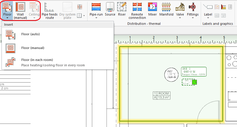
1. Inserting 供热/供冷区 - Cut out appropriate fragments of: 供热/供冷区 and/or change their shapes to adapt them to occupied areas (stairs, bathtubs) in rooms.
- Divide selected areas of 供热/供冷区 with regard to required expansion allowances.
- Declare and set up the 外区.
更多信息,见: Peripheral zones of heating/cooling areas zone

分/集水器
- Insert 分/集水器 on every storey. 分/集水器 is inserted in the drawing together with manifold cabinet.
更多信息,见: Manifold and accessories

引线管路径
- Connect 供热/供冷区 with manifolds using 引线管路径. 引线管路径 enables automatic generation of pipe feeds.
更多信息,见: Editing pipe feeds in a radiant system

Edit installation - feed to manifolds
源
- Insert 源 on the lowermost storey.
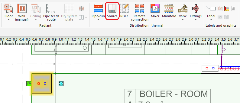
4. Inserting 源

立管
- Insert 立管, assign a symbol to it and define its extent (from storey 0 to storey 1).
更多信息,见: Connecting storeys with the "Stack" element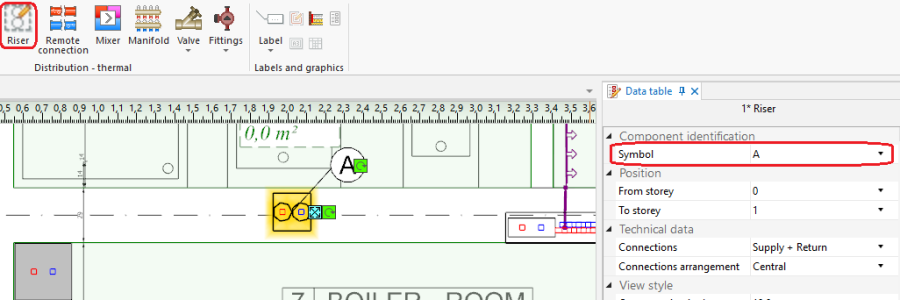
5. Inserting 立管

Distribution
- Connect 源, 分/集水器, 立管 with each other by drawing the network using the 管路 component and the 捕捉 and 定向线 modes.
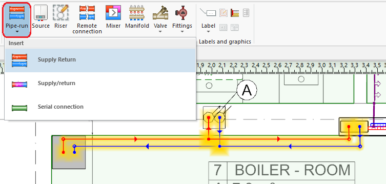
6. Connecting system components

Fittings
- Insert 阀门 onto pipe-runs.
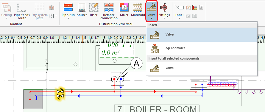
7. Inserting Fittings - Select 阀门型号 in 参数表.
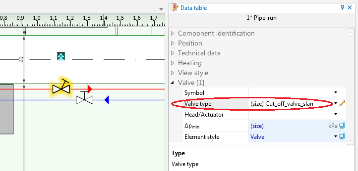
8. 阀门型号 - Use Copy - Paste to insert fittings of the same type onto other pipe-runs.


Verify correctness of installation structure
- Verify the correctness of the installation structure using the 检查连接 function (Key shortcut: Shift + F2).
- Verify the correctness of the installation structure and find conflicts using 3D视图.
更多信息,见: Verification of the correctness of installation structure
Edit installation components data
表面装饰层
- Mark selected 供热/供冷区 components and specify the type of 表面装饰层.
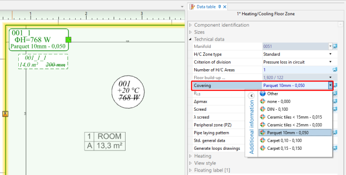
9. 表面装饰层

供热/供冷区
- Mark these 供热/供冷区s where significant surface area is occupied by pipe feeds and change their type to 由引线管供热/供冷. Remember in this case to remove connections with the manifold.
- Mark these 供热/供冷区s where no loops are to be arranged and change their type to 无管材.
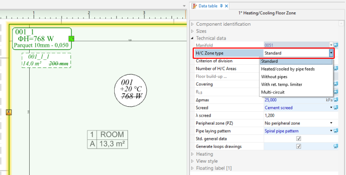
10. Type 供热/供冷区

Calculations and diagnostics
Radiant system calculations
- Launch complete calculations by clicking the
 icon in the 计算 section of the toolbar.
 - Open the 诊断 window by selecting it in the list of windows or by pressing F8.
- After calculations are completed verify the messages listed in the 诊断 window. If error messages are displayed, these must be eliminated in the first place.

更多信息,见: Calculations and diagnostics
Modifying system parameters to adapt attained output to required output
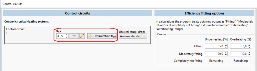
- Change feed temperature of the radiant system.
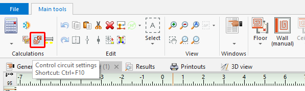
11. 
12. - Change pipe spacing and temperature drop in individual loops.
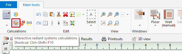
13. 交互式辐射系统计算 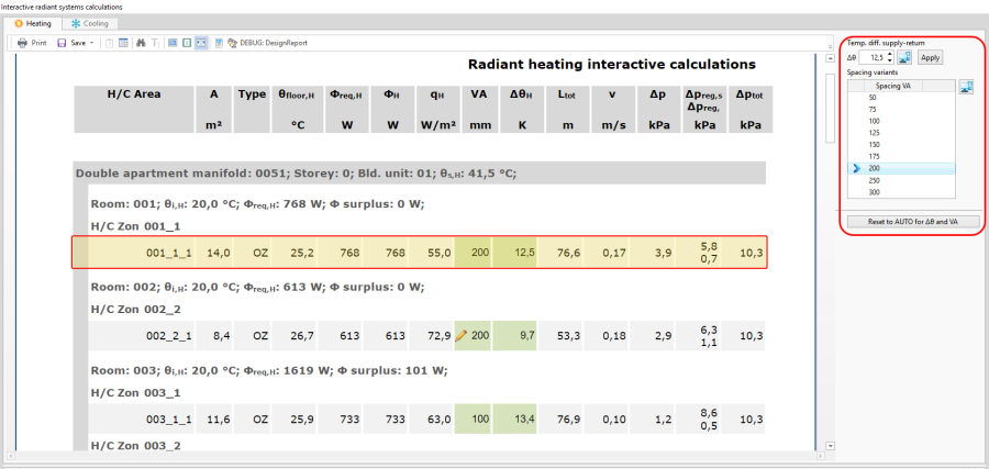
14. 交互式辐射系统计算 - Change structure of heating floor\wall.
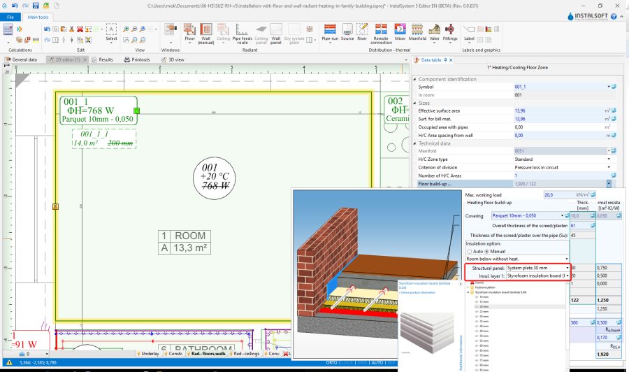
15. 地面构造 ... - Change 回路最大压降.
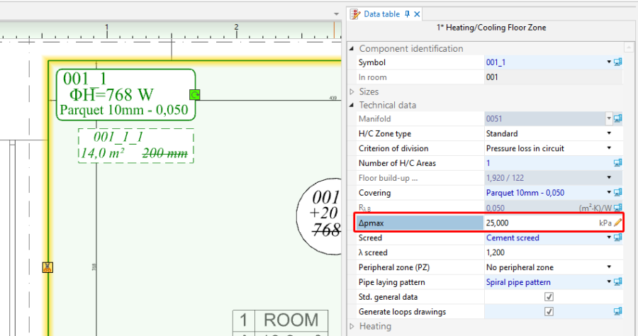
16. 回路最大压降


Recalculation and verification of results
- Verify calculation results paying special attention to:
- coverage of heat demand in rooms,
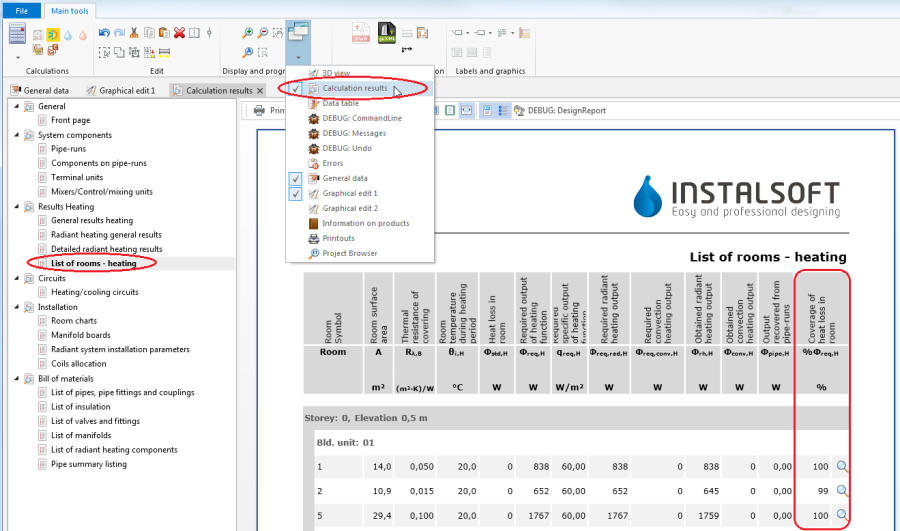
17. 所需供热输出的满足率 - sized layers in 供热/供冷地面, to see if there are no undesirable differences in height/thickness in adjacent areas.
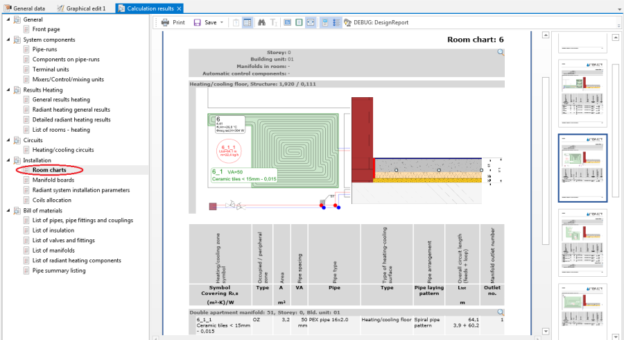
18. 地面构造 ... - bills of materials.
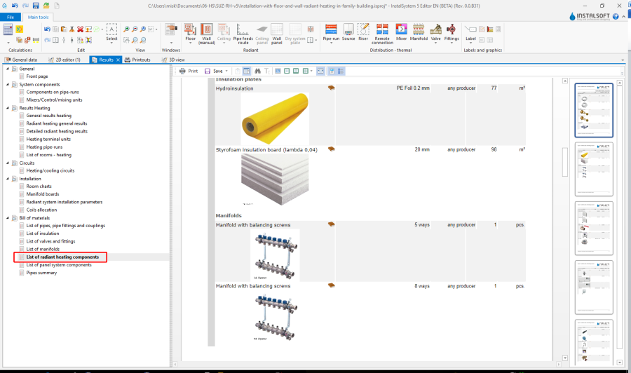
19. 材料清单 - 供暖 / 供冷 - 辐射供热部件清单
- coverage of heat demand in rooms,


Prepare drawing for printing/export
标签
- Insert required labels onto components.
- Configure the label appearance (opc).
更多信息,见: Item 5. Component appearance configuration and editing parameters configuration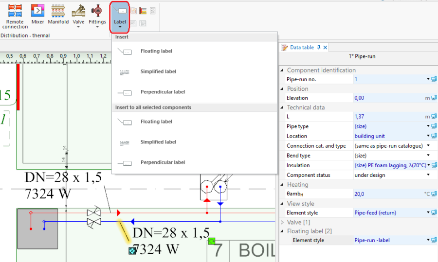
20. Inserting 标签

分集水器设置表
- Insert 分集水器设置表.
更多信息,见: Manifold label and table
盘管辐射构造断面图
- Insert 盘管辐射构造断面图. Rescale and configure, if necessary.
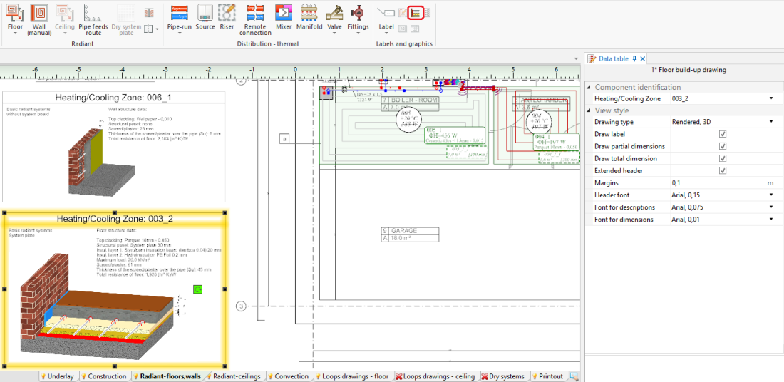
21. 盘管辐射构造断面图

辐射供暖供冷回路
- Automatically generate the 辐射供暖供冷回路 drawings.
更多信息,见: Automatic generation of loop drawings - Check the generated 辐射供暖供冷回路 drawings and modify them manually, if necessary.
更多信息,见: Manual editing of loop drawings
图框
- Insert 图框.
- Select 图框 in 参数表 .
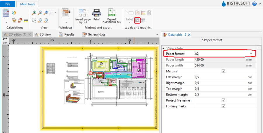
22. Inserting 图框

标题栏
- Insert 标题栏.
- Enter the required data in 参数表.
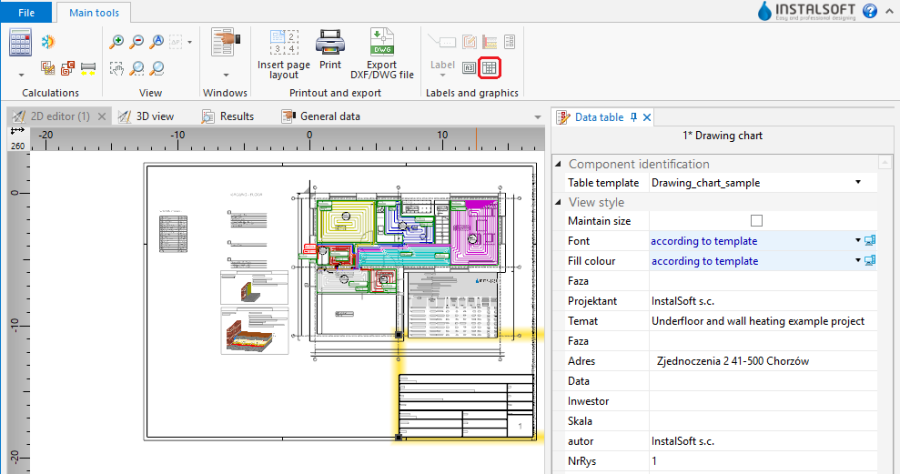
23.标题栏

Print/export results
- Print/export drawings.
- Print/export tables.
更多信息,见: Export / print results and drawings