线热桥和点热桥
跳转到导航
跳转到搜索
| 产品 | InstalSystem 5 |
| 文章类型 | 功能和工具 |
| 版本的最新内容 | 2025-04-22 |
说明
本文介绍了建筑热负荷计算中线性热桥和点热桥的计算方法。
在程序中的位置
热桥计算方法 的选择可以在一般参数 窗口的计算标准和选项 中找到。

应用举例
场景 I - 线性热桥简化的计算法
- 编辑默认参数:
- 在一般参数 窗口,建筑热负荷计算, 计算标准和选项 中,对于热桥计算方法,选择简化的。 注: 此方法适用于EN标准;
- (可选) 为热桥修正的方式 设置自动模式 。这将把建筑结构/建筑(房间视图)表格上所有的ΔUtb (热桥修正) 设置为自动模式,并使用如下默认值:
- ΔUtb = 0.05 W/(m2·K) - 对于外部围护结构 (外墙, 外窗, 外门, 户外地板, 屋顶) 以及对于与大地接触的围护结构 (地下部分墙体, 接地地板);
- ΔUtb = 0.00 W/(m2·K) - 对于内部围护结构 (内墙, 内部地板, 内门, 内窗).
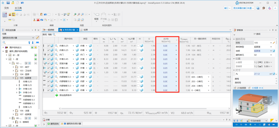
2. 处于自动模式 状态的ΔUtb
- (可选项) 针对DIN标准,引入了ΔU
- 编辑房间参数:
- 在建筑结构 / 建筑(房间视图)表格中,选择确定ΔUtb (热桥修正) 的方法:
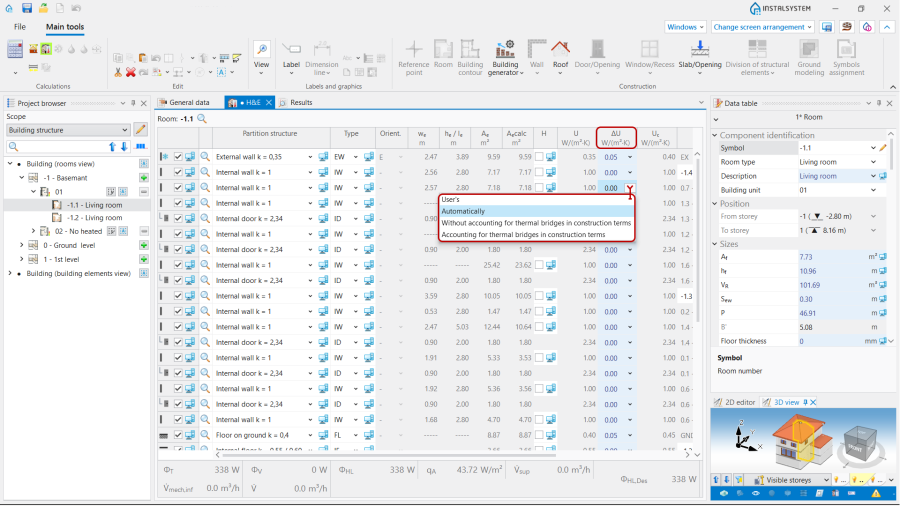
3. 热桥修正.
- 用户的 - 允许自己设置补偿值;
- 自动 - 根据自动 模式初始化该默认值;
- 在结构方面中没有考虑热桥 - ΔUtb = 0.05 W/(m2·K);
- 在结构方面考虑热桥 - ΔUtb = 0.1 W/(m2·K).
- 在建筑结构 / 建筑(房间视图)表格中,选择确定ΔUtb (热桥修正) 的方法:


场景 II - 依据 EN 12831 方法核算线性热桥
- 编辑默认参数:
- 在一般参数 窗口,建筑热负荷计算, 计算标准和选项 中,对于热桥计算方法 ,选择依据 EN 12831 。注: 本方法仅用于EN标准。
- 编辑房间参数:
- 在建筑结构 / 建筑(房间视图) 表格中,选择确定ΔUtb (热桥修正) 的方法, 类似于场景 I - 线性热桥简化的计算法。
Scenario III - 自动 - 基于传热模型 method of accounting linear thermal bridges
- Editing the default data:
- In the 一般参数 window, 建筑热负荷计算, 计算标准和选项 tab choose 自动 - 基于传热模型 for the 热桥计算方法. Note: this method is available for the EN standards.
- Definition of default types of the linear thermal bridges:
- After making 计算 the 热负荷计算(TB) (传热计算中的热桥) scope with the representation of thermal bridges will be available in 2D编辑器 and on 3D视图. Open 项目浏览器, 建筑热负荷计算, 热桥的定义. Select the default definition for each type of linear thermal bridge from the offered visualized variants. Note: One definition per bridge type is available by default.
Once a linear bridge is defined, its description will be available in the working space and in the 参数表:- 名称,
- 热桥类别,
- 热桥定义 (from the visualized variants),
- Ψ, W/(m·K) (线性热桥的传热系数).
- (Optionally) Copy an existing thermal bridge definition and modify its data, indicate as default;
- (Optionally) Create a new bridge definition, manually complete its data, select a bridge category from the list and indicate as default;
- (Optionally) Deletion of selected user definitions of bridges.
- After making 计算 the 热负荷计算(TB) (传热计算中的热桥) scope with the representation of thermal bridges will be available in 2D编辑器 and on 3D视图. Open 项目浏览器, 建筑热负荷计算, 热桥的定义. Select the default definition for each type of linear thermal bridge from the offered visualized variants. Note: One definition per bridge type is available by default.
- Perform 计算, resulting in automatic detection of linear thermal bridges and their inclusion in the 建筑热负荷计算;
- Overview of automatically recognized linear thermal bridges and make manual edits, if necessary:
- Open 项目浏览器, 建筑热负荷计算, 热桥视图. The tree presents the linear bridges within the rooms grouped by type in the related branches. All the bridges of a given type within a room can be selected using the 选择所有 function or by the 框选当前楼层中指定类型的部件. Multi-selection with CTRL/SHIFT is also possible;
- The сhosen bridges are presented in the 2D编辑器 window and 3D视图 on a separate edit scope 热负荷计算(TB).
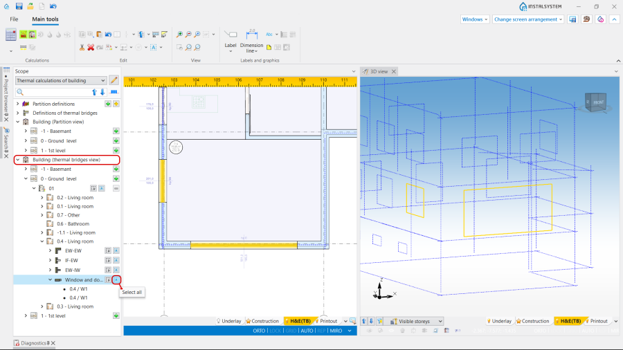
4. 热桥视图. - The selection of linear thermal bridges directly in the 2D编辑器 window or 3D视图 is also possible in the 热负荷计算(TB) scope by clicking on its graphic representation;
- The linear thermal bridges of a defined type can be selected with the use of the buttons available at the 热桥的定义;
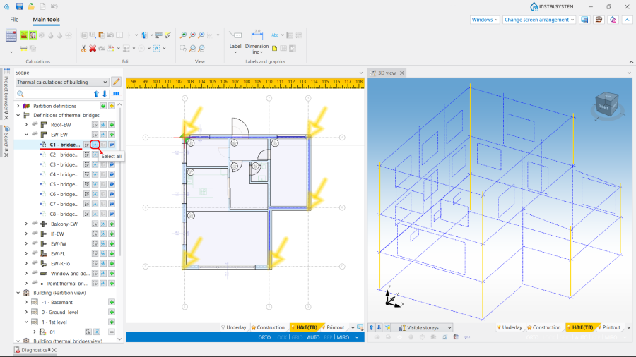
5. Selection of thermal bridges of a defined type. - Manual editing of automatically assigned thermal bridges:
- The operations, available for the selected thermal bridge, are the following:
- Manual change of 热桥定义;
- Manual correction of the I ( 热桥的长度) of a linear thermal bridge.
- Unchecking check box 计算时考虑;
- Change of 部件样式 and addition of 说明.
- The operations, available for the selected thermal bridge, are the following:


Scenario IV - Method of accounting point thermal bridges
- Editing the default data:
- In the 一般参数 window, 建筑热负荷计算, 计算标准和选项 tab choose 自动 - 基于传热模型 for the 热桥计算方法. Note: this method is available for the EN standards.
- Definition of point thermal bridges:
- After making 计算 the 热负荷计算(TB) (传热计算中的热桥) scope with the representation of thermal bridges will be available in 2D编辑器 and on 3D视图. Open 项目浏览器, 建筑热负荷计算, 热桥的定义, 点热桥. Select point thermal bridge type from the offered list;
- The data of the selected type will be available in the 参数表:
- 名称,
- 说明,
- 点传热值 (点传热值),
- 包含点热桥的围护结构定义 - when opening the field the definition grouped for the partitions will be available. This is possible to select one or more partition definitions,
- 说明 with two variants to choose from: 围护结构每平方米 and 每个围护结构,
- 点热桥的数量. Note: The correction of this field is also possible after making 计算.
- (Optionally) Copying an existing 热桥定义 and modifying its data as above (e.g. to include the same bridge in different 外墙 definitions);
- (Optionally) Creating a new bridge definition, manually filling in the above data;
- (Optionally) Deletion of selected user definitions of bridges.
- Perform 计算, resulting in automatic detection of point thermal bridges and their inclusion in the 建筑热负荷计算;
- Overview of automatically recognized point thermal bridges and make manual edits, if necessary:
- Open 项目浏览器, 建筑热负荷计算, 热桥视图. After deploying the tree at the 房间 level, an expandable 点热桥 branch is available below the branches with linear thermal bridge types,
- The сhosen bridges are presented in the 2D编辑器 window and 3D视图 on a separate edit scope 热负荷计算(TB).
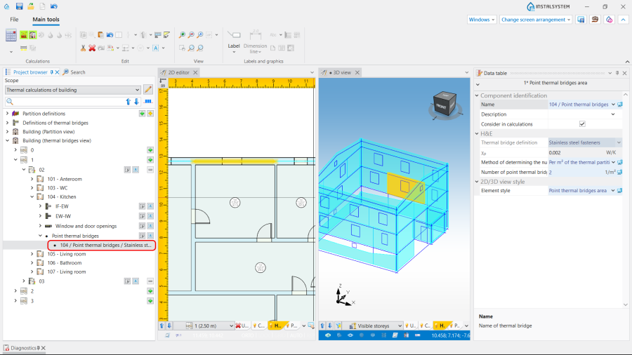
6. 点热桥. - Manual editing of the point bridge area data:
- The operations, available for the selected thermal bridge, are the following:
- Change of 确定点热桥数量的方法, status AUTO / MANUAL (
 /
/  ):
):
- AUTO allows to determine the 点热桥的数量 according to bridge definition.
- MANUAL gives the possibility to change the default method and to define individually the 点热桥的数量 to be taken into account (via the fields 围护结构每平方米 or 每个围护结构).
- Unchecking check box 计算时考虑;
- Change of 部件样式 and addition of 说明.
- Change of 确定点热桥数量的方法, status AUTO / MANUAL (
- The operations, available for the selected thermal bridge, are the following:
