机械通风系统的设计
| 产品 | InstalSystem 5 |
| 文章类型 | 设计课程 |
| 版本的最新内容 | 2024-07-29 |
课程内容
本文介绍了基于现成部件为住宅建筑开展通风系统计算 的基本设计方法。
模块和程序的配置
InstalSystem 5 需带有如下模块:
- .
项目文件
本课程中使用的项目文件:住宅建筑中的机械通风系统设计(本课程的示范案例)。
初始状态
该项目文件包含模板文件中配置的完整默认参数。建筑结构已根据DWG布局进行了详细说明。
操作步骤
打开项目文件
- 创建新项目时,从列表中选择包含通风系统默认参数的模板,或者,
- 导入包含带有建筑结构的项目文件 - 至少包含正确的坐标、楼板厚度和手动创建的房间.
定义项目的一般参数
在一般参数 窗口,填写默认参数:
- 项目范围 - 选择项目范围: 通风系统计算 。

1. 项目范围. - 目录 – 选择必要的目录并将其移动到项目可用的产品目录 表中。为了加快选择速度,可以使用过滤器。更多信息,见: Using catalogues and catalogues data in the project.
- 一般参数编辑:
- 楼层管理:
- 创建适当数量的楼层 / 子楼层 (通过IFC解析或手动创建);
- 设定楼层参数:
- ΔH通风, 刚性, 上板 - 刚性风管轴线与上方楼板的默认距离;
- ΔH通风, 柔性, 上板 - 柔性风管轴线与上方楼板的默认距离;
- ΔH通风, 墙送 - 墙面送风口与吊顶的默认距离;
- ΔH通风, 墙回 - 墙面回风口与吊顶的默认距离;
- ΔH通风, 顶送 - 顶面送风口与吊顶的默认距离;
- ΔH通风, 顶回 - 顶面回风口与吊顶的默认距离;
- ΔH通风, 地送 - 地面送风口与地面的默认距离;
- ΔH通风, 地回 - 地面回风口与地面的默认距离.
- (可选) 房间参数 - 对于项目中使用的每种/选定的房间类型 ,设置以下值:
- 排风量 (V回), 送风量 (V送) 或最小通风换气次数 (n最小);
- 楼层管理:


- 通风系统计算 / 默认类型和参数 – append default types:
- 默认的管材类型和绝热材料: 刚性风管;
- 默认的管材类型和绝热材料: 柔性风管;
- 默认类型: 其它部件:
- 空气处理装置 / 热回收装置,
- 分风箱 / 集风箱,
- 墙面送风口 / 墙面回风口, 顶面送风口 / 顶面回风口, 地面送风口 / 地面回风口;
- 热回收效率: 根据目录参数, 根据热损失参数 or 用户指定;
- (可选) 在系统的不同位置指定和调整 V最大, m/s 的默认值。
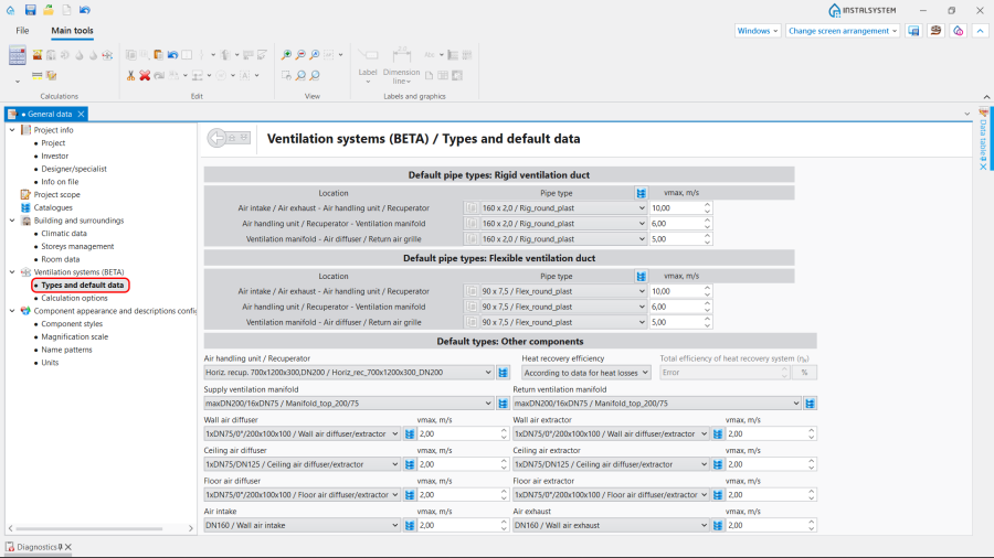
3. 默认类型和参数.
- 通风系统计算 / 计算选项:
- 选择通风量的确定方法;
- (可选) 启用检查每人的最小新风量 功能;
- (可选) 调整室外取风口 装置所吸入的θ室外 - 室外设计温度 值。

4. 计算选项.
- 通风系统计算 / 默认类型和参数 – append default types:


系统装置的编辑
编辑参数
设置或修改排风量 (V回), 送风量 (V送) 或在建筑 编辑器内为每个特定房间 ,在其参数表 中设定 最小通风换气次数 (n最小) 值。

编辑系统
使用捕捉 和定向线 模式,进行插入和图形的编辑操作。
- 选择编辑器通风.
- 插入通风 :
- 热回收装置,
- 分风箱 和集风箱;

6. Insert 热回收装置 and 分风箱.
- 插入通风 末端装置,如有必要,需指出 旋转角度 :
- 室外取风口,
- 室外排风口,
- 新风散流器(格栅、送风散流器),
- 回风口(室内吸风);

7. Insert 通风 terminals and indicate the 旋转角度.
- 插入立管;
- 使用刚性风管 或柔性风管 连接系统部件。


Editing the element data
In the case of necessity modify the 通风 elements data in the 参数表 window, in particular:
- 类型 of the 通风 terminal;
- V送 / V回 for the 通风 terminal;
- 距天花板或楼板的距离 / 标高 for the 热回收装置;
- 距天花板或楼板的距离 / 标高 for the 分风箱 and 集风箱;
- 距天花板或楼板的距离 / 标高 for the 风管;
- 管材类型 for the 风管.
Verifying the correctness of the installation structure.
- Verify the correctness of the connections of the installation components using the 检查连接 function (Shortcut: Shift + F2);
- Verify the correctness of the installation structure using the 3D视图;
- Adjust the layout of the 风管 according to external factors, e.g. passages through walls, overlaps with other installations.
Running the calculations
- Start the calculation of the 通风系统计算 by clicking
 in the 计算 section of the toolbar;
 - Сheck messages the 诊断 window;
- In the case of necessity verify and adjust the installation, for example:
- increase the Diameters / 尺寸 of the 风管, if 超过最大空气流速(%s m/s>%s m/s) in the duct;
- increase 尺寸 of the 送风口 / Air extractor or add more 风管 and 送风口 / Air extractor, if 超过最大空气流速(%s m/s>%s m/s) in the 通风 terminal;
- correct the values of V送 and V回, in the case of 送排风量不平衡(ΣV送 =%s m3/h,ΣV回) = %s m3/h) .
Verification of results
- After calculations, the system layout should be verified visually by means of the 3D视图;
- If the calculations end with at least one error, the layout may be unreliable;
- The data of each 通风 element can be verified directly in the drawings.

8. Visual verification in the 3D视图 window. - Other forms of presentation of calculation results are: component labels and tables of results 更多信息,见: Presentation of the calculations result.

9. 结果 - 通风.


Preparing drawings for export/printing
- To have the results for 通风 installation elements included in the printout of a drawing, appropriate labels must be inserted 更多信息,见: Preparation of drawings for export / printing.
- Completed drawings can be printed and/or exported 更多信息,见: Export / print results and drawings.