排水系统的设计
| 产品 | InstalSystem 5 |
| 文章类型 | DESIGNING LESSON |
| 版本的最新内容 | 2021-12-17 |
Scope of lesson
This article presents the basic design path for the internal gravity sanitary sewerage system between the sanitary fixtures and the building outlet.
Modules and program configuration
- InstalSystem 5 with the module:
- 室内重力排水系统
Initial state
The project contains complete default data configured in the template file. The building structure has been elaborated on the basis of DWG layouts.
Steps to perform
Opening the project file
- When creating a new design, select from the list the template that contains the default data for the drainage system
- (or): upload an existing building structure file - minimum content is correct ordinates and slab thicknesses. If the design was created with a configuration that did not include the drainage system, import the drainage system general data from the appropriate template.
更多信息,见: Template files
| 项目文件
|
Initial state, isproj Sewage installation, isproj |
| 设计时使用 | InstalSystem 5 Rev. 22.1 |
| 所需模块 | 基本模块 室内重力排水系统 |
| 项目范围 | Sewage installation |
| 所用的产品目录 |
Standard water taps and whiteware |
| 建筑类型 | residential building with basement 3-storey |
| 建筑结构 | Base drawing all storeys, dwg |
| 图纸范围 | Plan view |
| 设计者 |  www.instalsoft.com |
| 法律免责声明 | The whole file or parts of the project may be copied |
| 计算结果 | Results, pdf |
| 设计图纸 | Full printout, dwg Storage, pdf Ground floor, pdf Attic floor, pdf |
Editing the general project data
Enable 排水系统计算.
Verify data that affect significantly the geometry of the drainage system, unique to each project:
- default depth of the drainage outlet to the external network (relative to the design 'zero' level), taking also into account the ground level
- floor thickness specifications (layers placed on the floor slab) on individual storeys - ATTENTION! this may affect previously completed or planned designs of other systems in this file. Drainage fixtures are positioned on the floor or at a predetermined distance from the floor surface.
Further adjustment of the general data may be necessary when work is started on a file created without a drainage module and without a dedicated design template:
- In the 排水系统计算 tab specify:
- 计算标准和选项:
- In the 计算标准 tab select the one appropriate for the market region,
- 建筑类型,
- specify mimimum gradients in accordance with design requirements and applicable regulations,
- Indicate the default direction for the 器具排水管的连接方向控制,
- For the selected direction define the default value of the 排水横支管在立管上的连接点与地面完成面的距离 - which will be applied on all storeys in the project, and which then can be individually modified on selected storeys,
- Default pipe-run fill ratio.
- 计算标准和选项:

- In the 水力分配系统 tab specify 默认类型和参数 for each component with regard to,
- 默认的管材类型: 排水 / 通气管 for the various pipe-run locations,
- 管路连接的默认方式 - the picklists depend on the content of default pipe catalogues for the given location,
- 默认类型: 其它部件.

- In the 卫生器具 table assign data with regard to:
- 默认的连接系统 - from the pipe folder specified for the connections select the appropriate system for the given fixture type,
- 其它卫生器具的连接系统 - common selection for the remianing fixture types.

- Editing data in the 楼层管理 project section
- For storeys with a drainage network, determine the required value of 排水立管转成排水横管的拐点, "Auto" means letting the program decide this depending on the location of the sewage outlet. By specifying a value manually, we can e.g. impose the location of the main sewer under the basement ceiling.
- 器具排水管的连接方向控制 - change if on a given storey the value is different from that set out in the general data above,
- 排水横支管在立管上的连接点与地面完成面的距离 - negative values mean placing junctions on risers in plumbing shafts within a floor or ceiling slab, which may be necessary to maintain proper gradients from low-placed fixture outlets.

Editing the installation and its data
Editing the installation structure
- Insert sanitary appliances, if these were not included in the file, e.g. from a previously completed design of water supply system 更多信息,见: Editing sanitary installation,
- Define the location and data for the 立管: range of storeys, termination 通气管,
- Insert the 生活污水排出口 and verify its position in the model,
- Connect the appliances with the 立管 using the 管路 components. ATTENTION! In the drainage system this component always consists of a single section.
- On the storey where 生活污水排出口 is placed, connect it with the 立管, to form the collector sewer. The collector sewer elevation is by default adjusted to the posion of the 生活污水排出口, unless the value of 排水立管转成排水横管的拐点 has been specified manually.
Verifying the correctness of the installation structure.
- Verify the connectness of the connections of the installation components using the 检查连接 function (Shortcut: Shift + F2). ATTENTION! For some types of appliances where the approach direction should be perpendicular to the object (e.g. toilet with a tail outlet), this function automatically creates short pipe-runs immediately next to the appliance to ensure this perpendicularity.
- Verify the correctness of the installation structure and detect collisions with other systems using the 3D视图, if necessary, enabling the view of other editing ranges, it is advisable to turn off the display of walls
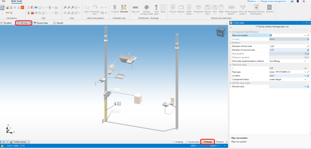
5. Verifying the correctness of the drainage installation structure using the 3D视图 - Verify provisionally the vertical routing of pipe-runs in the model (calculations may alter this).
- Specify, if necessary: the elevations of the ends of the pipe-runs (paying attention to constraints resulting from their connection to other components), the actual gradients of pipe-runs.

ATTENTION! Following such changes, verification must be repeated.
Editing installation components data
- Verify and adjust the drainage-specific data of the appliances (DU, outlet diameter)
- If necessary, verify and adjust pipe-run data other than the default (pipe type, diameter setting, location)
Running the calculations
If no errors are found during verification, start the calculation of the 排水系统计算 by clicking  in the 计算 section of the toolbar.
The calculations finally determine the vertical routing of the pipe-runs.
Verification of results
- After calculations, the system layout should be verified visually by means of the 3D view
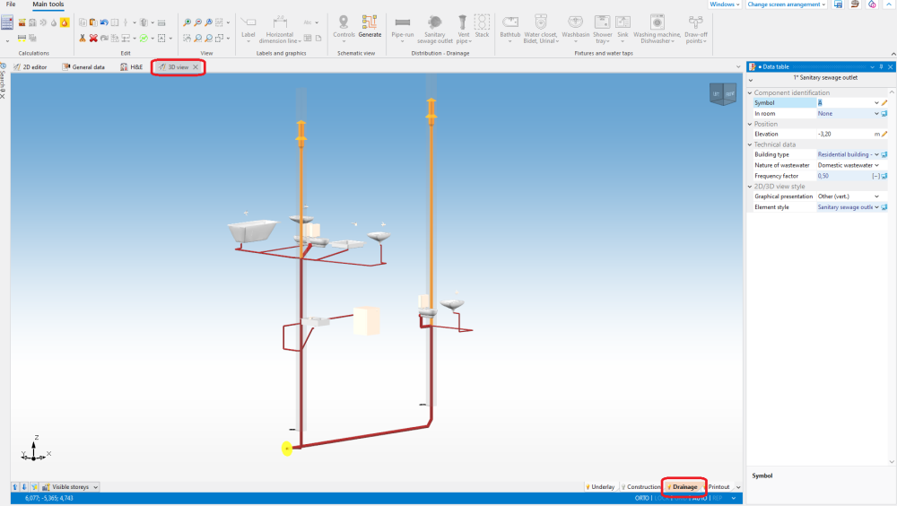
6. Visual verification of pipe routing using the 3D视图 function - The dimensioned diameters of the pipe-runs and fittings can be verified directly in the drawings
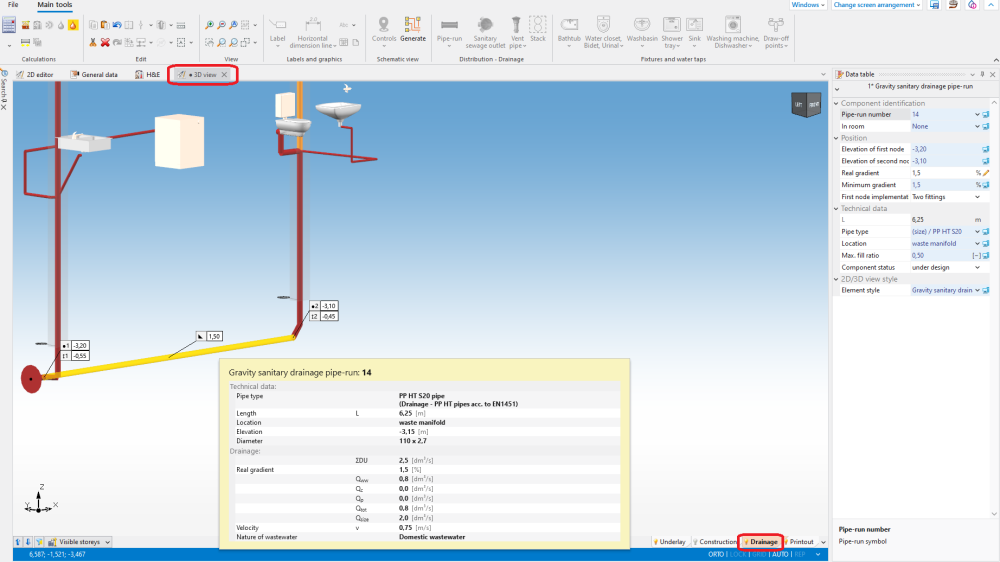
7. Verification of the dimensioned pipe-run diameters using the pipe-run properties window - Other forms of presentation of calculation results are component labels and tables of results 更多信息,见: Presentation of the calculations result
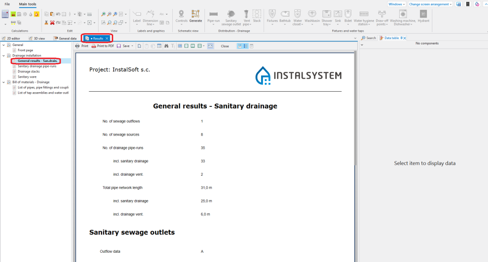
8. 一般结果 - 排水


Generating schematic views
The schematic view will be generated automatically as described 更多信息,见: Automatically generate schematic views
Preparing drawings for export/printing
- To have the results for pipe-runs included in the printout, labels must be inserted 更多信息,见: Preparation of drawings for export / printing
- Completed drawings can be printed and/or exported 更多信息,见: Export / print results and drawings