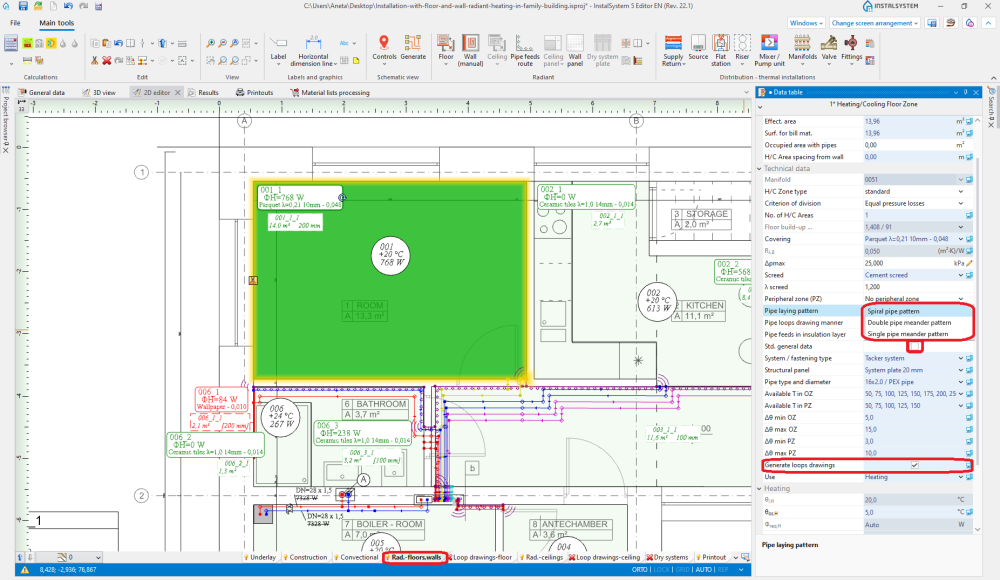
对于每一回路指出盘管方向。这可借助于图像指示器 来确定,一旦回形出现了改变盘管方向的指示器 , 在选择了它供热/供冷面之后就可用它来改变盘管的方向。若要重新给指示器定位,则在指示器上按住鼠标左键,并带着紫色箭头将其拖动到所需要的盘管方向上。如果有单管蛇形/双管蛇形, 两个指示器出现two indicators are available: for changing direction of pipe laying and for selecting the side parallel to the meandering direction .
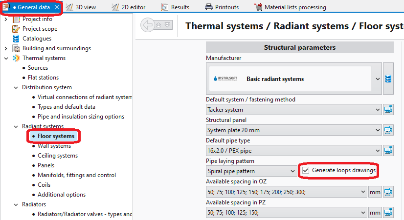
Recalculate the project . After recalculation the drawings of the loops are generated automatically.
If necessary, correct the pipe laying direction by relocating the graphic indicators and recalculate the project to refresh the loop drawings.
Manual editing of loop drawings
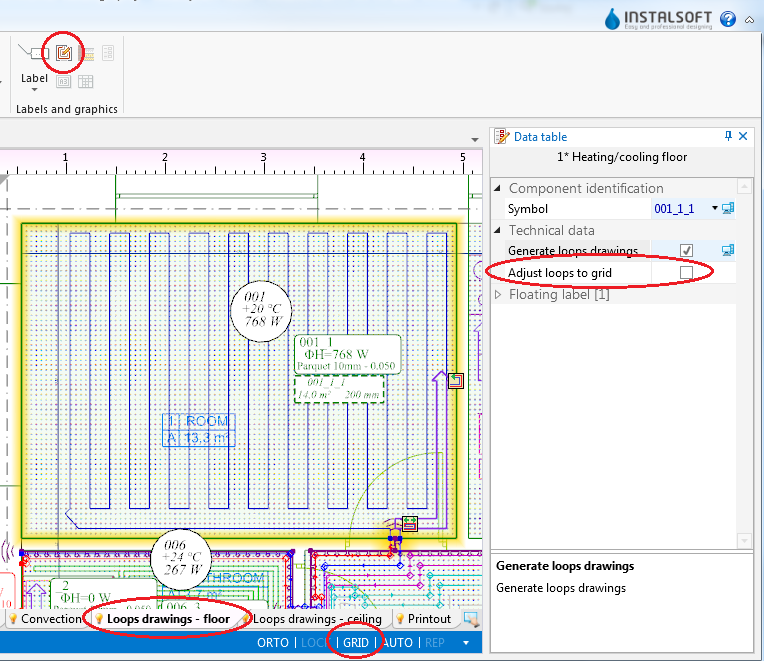
Disable generation of loop drawings for selected components 供热/供冷面. Attention! Clearing the 自动绘制盘管图 option does not remove existing drawings of loops, it only freezes them in their current state and enables manual editing or deleting thereof.
Enable the 栅格 mode which helps in correcting or manual drawing of loops. Grid nodes are arranged at the minimum distance allowable for the selected pipe laying pattern. Colours of grid nodes are repeated for the current pipe spacing, which facilitates drawing with the use of that spacing. The grid can be arranged parallel to selected edge of component 地面供热/供冷区 by positioning on that edge the blue hot-point . It becomes available when component 地面供热/供冷区 is selected.
Correct/draw manually selected segments of loop.
Additional information
Graphic style - in order to improve the legibility of loop printouts, one can:
use component appearance style where zones of heating/cooling surfaces are transparent,
disable structure display or remove base drawing,
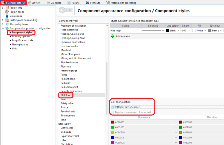
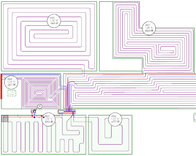
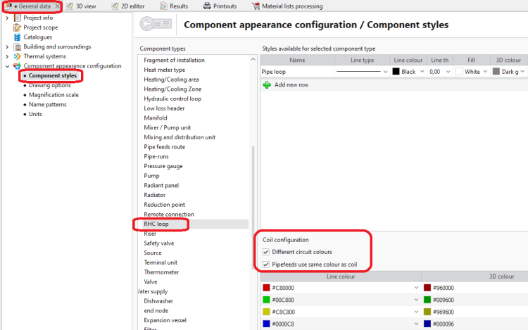
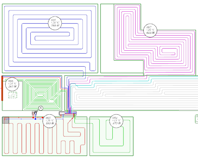
select manner of loop display where loops differ in colour and pipe feeds are of the same colour as the corresponding loops
4. Component styles - no colour difference between loops5. Graphical editing - no colour difference between loops
6. Component styles - loops differ in colour7. Graphical editing - loops differ in colour
Diagnostics - when the program is not able to generate a loop drawing for a given component, a warning is displayed in the diagnostics window. To rectify this, either the pipe laying parameters have to be adjusted or the 自动绘制盘管图 checkbox must be cleared and the drawing modified manually. Manual modification may also be applied when the automatically generated drawing does not satisfy the user's expectations.



 , 在选择了它供热/供冷面之后就可用它来改变盘管的方向。若要重新给指示器定位,则在指示器上按住鼠标左键,并带着紫色箭头将其拖动到所需要的盘管方向上。如果有单管蛇形/双管蛇形, 两个指示器出现two indicators are available: for changing direction of pipe laying
  .
. . After recalculation the drawings of the loops are generated automatically.


 . It becomes available when component 地面供热/供冷区 is selected.


