自动创建系统示意图
| 产品 | InstalSystem 5 |
| 文章类型 | 功能和工具 |
| 版本的最新内容 | REVISION Rev. 17.1 |
说明
本文介绍了基于应用: 供热系统 或 应用: 供冷系统 类型的系统安装模型自动创建示意图的方法。自动创建的示意图还具有手动编辑、插入配件和随时再重新生成视图的选项。
系统安装示意图通过在2D编辑器中使用起始点 (供热供冷系统) 来生成。
本功能目前正在开发中,已包含在BETA版本中
在程序中的位置
用于控制示意图自动生成的组件和功能图标可在主工具 的2D编辑器 窗口内的对流 、地面/墙面辐射 、顶面辐射 编辑器内找到。

所生成的工作表类型: 示意图 位于工作表清单的底部。

应用举例
检查连接
为正确生成示意图,有必要使用检查连接 功能或按下Shift+F2键来检查一下连接的正确性。项目文件可以包含错误,但不予许包含任何连接错误。
用于控制示意图自动生成的基本部件和功能的介绍
起始点 (供热供冷系统)
这是所生成的系统安装示意图的起点。必须给起点命名一个唯一的符号。允许插入多个起始点 (供热供冷系统),并且每个标识都可生成一个工作表类型: 示意图 
起始点 (供热供冷系统) 可放在如下部件上:
- 源
- 立管
- 管线对
- 分/集水器
- 户用换热机组
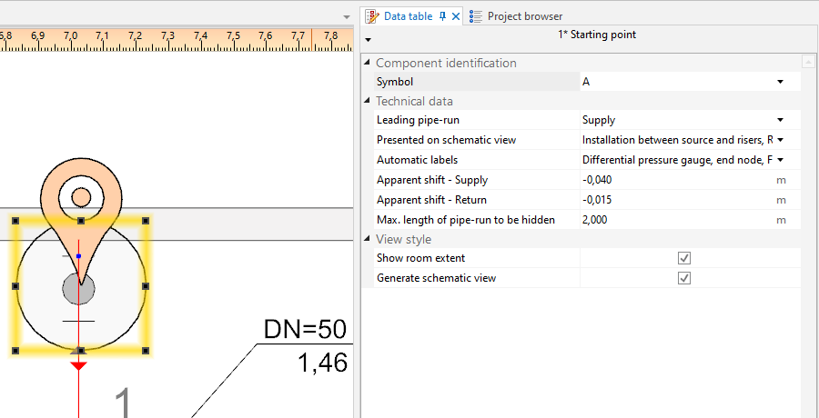
3. 起始点 (供热供冷系统)

- 领管路
生成示意图时具有优先权的管道的标识。这对产生不对称安装(沿不同路径布置供回管道)时非常重要。所有接点(三通、四通)也需标记在领管路上。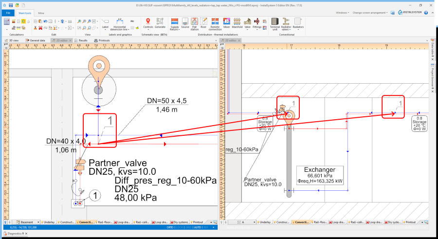
4. Junction (tee)
范围可以减小:- 源和立管之间的装置 - 生成从指示点到立管的示意图,不包括立管;
- 立管 - 生成从指示点到立管的示意图,包括立管;
- 立管后面的装置 - 生成从立管以外的指示点到终端设备的示意图。如果安装包括站,示意图终止于站;如果安装包括分集水器,示意图终止于分集水器。
- 户用换热站后面的装置 - 生成从指示点到站的示意图,包括站外的安装(必须选中立管后面的装置复选框。
- 分集水器后面的装置 - 生成分集水器以外的示意图 (必须勾选立管后面的装置 复选框)。
- 自动标签控制
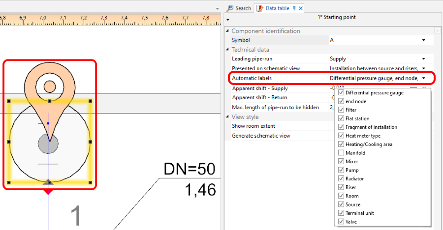
5. Schematic view - labels control - 标高的位移量
启用在示意图中显示同一标高(立面)上的管路。不影响模型中管路的标高。- 正值 - 该值将添加到示意图中供水管道的标高中。
- 负值 - 将从示意图中供水管道的标高中减去该值。
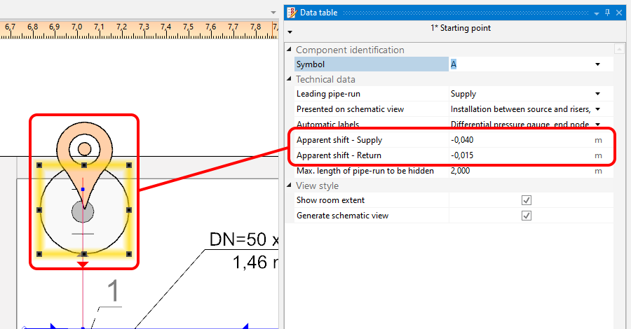
6. 标高的位移量 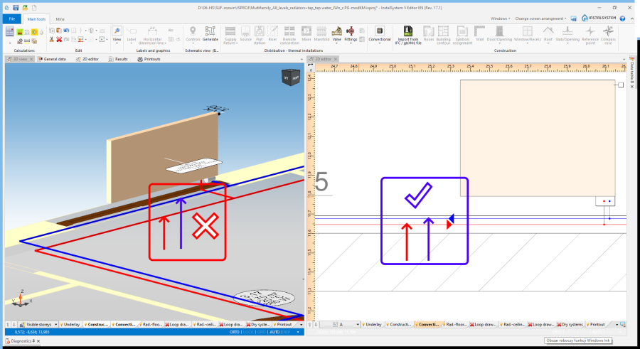
7. 标高的位移量 - 供回水
- 显示所有房间
所标记的房间及其标签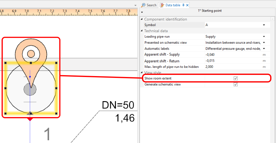
8. 显示所有房间 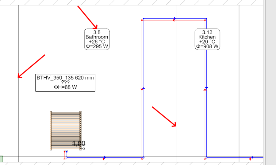
9. 显示所有房间 - 在示意图中的标出房间 - 创建示意图
不勾选此选项将在后续生成过程中禁用示意图的生成。例如,对于自动示意图控制功能的新设置将不予考虑。但是,禁用此选项不会影响安装系统部件。安装安装部件会自动刷新,即模型中安装部件的数量始终与示意图中安装部件的数量相对应。如果禁用此选项,图纸选择列表中将显示一个挂锁图标。


Unchecking this option disables the generation of the schematic view during subsequent generations, e.g. new settings for the automatic schematic view control functions will not be taken into account. However, disabling this option does not affect installation components. The installation components are refreshed automatically, i.e. the number of installation components in the model always corresponds to the number of installation components in the schematic view. If this option is disabled, a padlock icon is shown in the sheet selection list  .
.

控制点
Enables controlling the direction of generation of individual pipe feeds on the schematic view and modification of the leading route. It must be placed on the leading pipe-run. The control point changes the course of the schematic view starting from the junction beyond which it was inserted. Many 控制点 components can be inserted and they can be placed in a 工作表类型: 示意图 or a 工作表类型: 平面图.

- 方向.
Specifies, for instance, whether a part of an installation (e.g.: 立管) is to be treated as placed to the right or to the left of the 源. Similarly, one can decide whether a part of the installation is to the right or to the left of a 立管. The video shows how two risers are moved in the schematic view to the left of the source.
- 示意图中有断点.
Enables modifying the leading route in the schematic view. The video shows how the leading route is changed in such a way that the critical route is presented as the first one.
终点
The schematic view of the part of installation that is beyond the 终点 is not generated. This part of installation is represented by a 系统部件. The 终点 must have a unique symbol assigned.
The video shows how a riser is removed from the schematic view.
Parts of installation that are not subject to automatic generation of schematic views
- Installations with ceiling panels.
- Installations with wall panels.
These parts are automatically terminated with a 系统部件.
Manual editing and configuring
- Inserting independent components.
The following components can be placed in a 工作表类型: 示意图:- additional labels (e.g.: pipe-run labels). The positions of the inserted labels can also be changed - these positions are maintained after the schematic view is regenerated,
- valves,
- fittings placed on pipe-runs,
- radiator fittings.
Additional information
- Project file created with InstalSystem 4 which includes a 工作表类型: 示意图 loaded into InstalSystem 5.
Such a sheet is not converted into a 工作表类型: 示意图 of InstalSystem 5 and it is removed when loading - appropriate diagnostic message is displayed.