添加辐射系统盘管图:修订间差异
跳转到导航
跳转到搜索
| 第30行: | 第30行: | ||
# 在一般数据中或对于选定的部件启用自动生成盘管图。 | # 在一般数据中或对于选定的部件启用自动生成盘管图。 | ||
# 对于所选择的部件可选择非省缺的盘管样式。 | # 对于所选择的部件可选择非省缺的盘管样式。 | ||
# | # 选择编辑范围 ''<IS_TS id=RysPetliPodlogoweCaption/>''/''<IS_TS id=RysPetliSufitoweCaption/>'' | ||
# | # 对于每一回路指出盘管方向。 This is done by means of ''Graphic indicators'' which are enabled after selecting ''<IS_TS id=strPGCh/>''. In the case of ''<IS_TS id=rsWariantUlozeniaPGSlimak/>'', indicator [[File:Direction.png|20 px|]] for changing direction of pipe laying is available. To reposition the indicator, press and hold the LMB on the indicator and drag it with the purple arrow in the desired direction of pipe laying. In the case of ''<IS_TS id=rsWariantUlozeniaPGPojedynczyMeander/>''/''<IS_TS id=rsWariantUlozeniaPGPodwojnyMeander/>'', two indicators are available: for changing direction of pipe laying [[File:Direction.png|20 px|]] and for selecting the side parallel to the meandering direction [[File:Side.png|20 px|]]. | ||
# Recalculate the project [[File:Loops-calculation.png|40 px]]. After recalculation the drawings of the loops are generated automatically.<br clear="all"/> | # Recalculate the project [[File:Loops-calculation.png|40 px]]. After recalculation the drawings of the loops are generated automatically.<br clear="all"/> | ||
# If necessary, correct the pipe laying direction by relocating the graphic indicators and recalculate the project to refresh the loop drawings. | # If necessary, correct the pipe laying direction by relocating the graphic indicators and recalculate the project to refresh the loop drawings. | ||
2016年10月20日 (四) 14:46的版本
| 产品 | InstalSystem 5 |
| 文章类型 | FUNCTIONALITY |
| 版本的最新内容 | IS 5.0 Beta 21 |
说明
供热/供冷面 部件(地板和天花板)可以附上盘管图。程序自动生成的盘管图,在每次重新计算时都会被刷新。盘管图可修改或添加,也可手动绘制。建议在设计的最后阶段,再手动编辑它。
在程序中的位置
- 一般参数 - 对于所有部件,通过选择复选框,可自动生成盘管图。
自动绘制盘管图

- 参数表 对于部件 地面供热/供冷区, 当在地面/墙面辐射/顶面辐射 编辑范围内工作时,可:
- 通过选择复选框自动绘制盘管图,可自动生成的盘管图; 在此对于所选择的部件不勾选复选框一般参数,就可禁用盘管图自动生成。
- 选择盘管样式
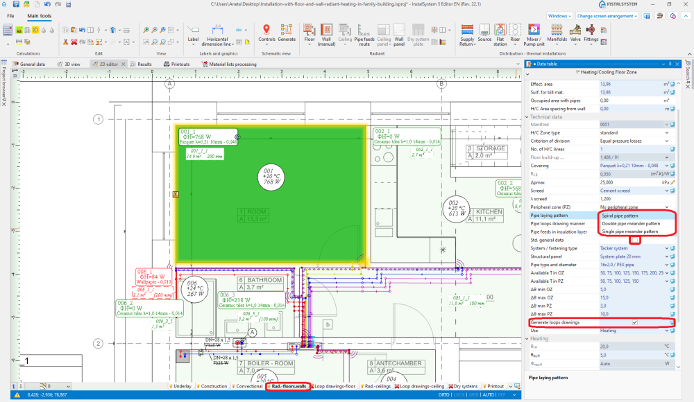
2. 盘管样式
- 当在地面盘管/顶面盘管编辑范围内工作时, 有一辐射供暖供冷回路工具,可进行手动绘制盘管图。使用该工具时,建议开启栅格栅格模式
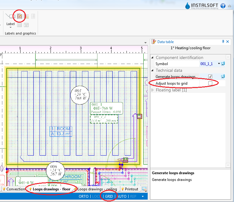
3. 盘管图 - 一般数据


应用举例
自动生成盘管图
- 在一般数据中或对于选定的部件启用自动生成盘管图。
- 对于所选择的部件可选择非省缺的盘管样式。
- 选择编辑范围 地面盘管/顶面盘管
- 对于每一回路指出盘管方向。 This is done by means of Graphic indicators which are enabled after selecting 供热/供冷面. In the case of 回形, indicator
 for changing direction of pipe laying is available. To reposition the indicator, press and hold the LMB on the indicator and drag it with the purple arrow in the desired direction of pipe laying. In the case of 单管蛇形/双管蛇形, two indicators are available: for changing direction of pipe laying and for selecting the side parallel to the meandering direction
  .
. - Recalculate the project
 . After recalculation the drawings of the loops are generated automatically.
 - If necessary, correct the pipe laying direction by relocating the graphic indicators and recalculate the project to refresh the loop drawings.


Manual editing of loop drawings
- Disable generation of loop drawings for selected components 供热/供冷面.
Attention! Clearing the 自动绘制盘管图 option does not remove existing drawings of loops, it only freezes them in their current state and enables manual editing or deleting thereof. - Enable the 栅格 mode which helps in correcting or manual drawing of loops. Grid nodes are arranged at the minimum distance allowable for the selected pipe laying pattern. Colours of grid nodes are repeated for the current pipe spacing, which facilitates drawing with the use of that spacing. The grid can be arranged parallel to selected edge of component 地面供热/供冷区 by positioning on that edge the blue hot-point
 . It becomes available when component 地面供热/供冷区 is selected.
 - Correct/draw manually selected segments of loop.

Additional information
- Graphic style - in order to improve the legibility of loop printouts, one can:
- use component appearance style where zones of heating/cooling surfaces are transparent,
- disable structure display or remove base drawing,
- select manner of loop display where loops differ in colour and pipe feeds are of the same colour as the corresponding loops


- Diagnostics - when the program is not able to generate a loop drawing for a given component, a warning is displayed in the diagnostics window. To rectify this, either the pipe laying parameters have to be adjusted or the 自动绘制盘管图 checkbox must be cleared and the drawing modified manually. Manual modification may also be applied when the automatically generated drawing does not satisfy the user's expectations.