管路:修订间差异
| 第83行: | 第83行: | ||
===在单个垂直平面中敷设管路=== | ===在单个垂直平面中敷设管路=== | ||
* 在''<IS_TS id=DataEditorTable/>'' 窗口中,对于某一''<IS_TS id=iNameKondygnacja/>'' 的''<IS_TS id=OgrzewanieChlodzenie/>'' 或''<IS_TS id=strInstalacjaWodociag/>'' 中的各种类型管路设定适当的标高值,并在''<IS_TS id=iName2Dzialki/>''/ ''三根管路'' 的''<IS_TS id=DataEditorTable/>'' 窗口的''<IS_TS id=strpnMultiPiperunDistance/>'' 中指定最小值,以便在一个垂直平面对齐管道,例如,在墙上一个接一个。 | * 在''<IS_TS id=DataEditorTable/>'' 窗口中,对于某一''<IS_TS id=iNameKondygnacja/>'' 的''<IS_TS id=OgrzewanieChlodzenie/>'' 或''<IS_TS id=strInstalacjaWodociag/>'' 中的各种类型管路设定适当的标高值,并在''<IS_TS id=iName2Dzialki/>''/ ''三根管路'' 的''<IS_TS id=DataEditorTable/>'' 窗口的''<IS_TS id=strpnMultiPiperunDistance/>'' 中指定最小值,以便在一个垂直平面对齐管道,例如,在墙上一个接一个。<br/> {{#ev:youtube|BDDmTIqseYU|900||||rel=0}} <br clear="all"/> | ||
===Inclined pipe-runs=== | ===Inclined pipe-runs=== | ||
2023年2月25日 (六) 10:08的版本
| 产品 | InstalSystem 5 |
| 文章类型 | 功能和工具 |
| 版本的最新内容 | 2023-01-10 |
说明
管路 是一个在所有设计范围内都需使用的部件,它在两个连接点之间形成了管道系统的一部分,并在连接点处可以改变水流。在以下范围内:供热系统计算 ,供冷系统计算 和给水系统计算 中,一段管路 可以由多个管段(垂直和水平)组成,并由管路分割点分隔。可以绘制单根管路,也可以绘制管线对 /三根管路 。在生活排水系统计算 范围内,重力排水 或通气管 的管路 始终由单根管段组成。 可以在楼层管理的参数中设定各种管路与地面的距离 省缺值。此外,用户可以使用2D编辑器 和3D视图 中的专用编辑器完全控制管路的布置。
在程序中的位置
插入管路
- 当勾选了项目范围 :供热系统计算 或供冷系统计算 ,在2D编辑器 窗口,进入:对流 、地面/墙面辐射 或顶面辐射 编辑器,就可在主工具 选项卡的水力分配 - 供热供冷系统 工具栏内找到与管路 相关联的图标。
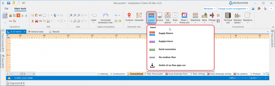
1. 管路 - 供热系统计算 或供冷系统计算. - 当勾选了给水系统计算 ,在2D编辑器 窗口,进入给水系统 编辑器,就可在主工具 选项卡, 水力分配 - 给水系统 工具栏内,看到与管路 相关的图标。

2. 管路 - 给水系统计算. - 当勾选了生活排水系统计算 , 在2D编辑器 窗口,进入室内排水 编辑器,就可在主工具 选项卡, 排水 工具栏内就可看到与管路 相关的图标。

3. 管路 - 生活排水系统计算.


应用举例
管路分割点和中点
- 一根管路 可以由多个通过中点连接的管段组成。
- 两根管路 由管路分割点,也就是通过一个接头/节点分开。
- 可以使用关联菜单和其中可用的功能在管路 上放置任意数量的附加点:插入中间点 和 插入分割点。
- 中点可以更改为分界点,反之亦然:
管路与地面以及管路与天花板之间的省缺距离
在参数表 窗口,在如下的区域中,可为每一楼层 的每种管路 设定它们与地面的省缺距离,并可为顶面辐射板的布置设定每种管路 与天花板的省缺距离:
- 对于供热系统计算 和供热系统计算 :
- ΔH管路,供 和ΔH管路, 回 - 在楼层参数中指定的管路至地面之间的距离(不适用于顶面辐射板的输配管路)。符号中的供指供水,回指回水
- ΔH管路.辐射板 - 顶面辐射板输配管路至天花板的距离
- 对于给水系统计算 :
- ΔH管路,热水 - 管路至地面的默认距离(在一般参数的楼层管理中设置) 对于管路 :热水
- ΔH管路,冷水 - 管路至地面的默认距离(在一般参数的楼层管理中设置) 对于管路 :冷水
- ΔH管路,循环 - 管路至地面的默认距离(在一般参数的楼层管理中设置) 对于管路 :循环

4. 省缺的管路距离

管道敷设距离
- 在参数表 窗口中,可以为管线对 /三根管路 指定它们之间的距离 。在管路部件插入后,程序将记住最后指定的距离,以便下次使用时再次使用该值。

5. 管线对的距离

确定供热系统计算、供冷系统计算和给水系统计算中管路的竖向对齐
可以在2D编辑器 和3D视图 窗口中,选择部件后显示的专用编辑器来管理管路的对齐和标高:
 - 显示管路端点的标高
 - 显示某一段管路的标高
 - 显示管路某一点/一段与地面的距离
6. 在2D编辑器 和3D视图 窗口中,显示管路的标高

InstalSystem 5 InstalSystem 5 提供了三种管理输配管路系统对齐的方法,它允许选择最方便的方法来适应各个设计环境。该方法应在管路 的参数表 窗口,管道标高设置 编辑器中进行选择:
- 自动 模式:
- 编辑器显示管路末端的标高和距地面的距离并呈灰色,该值无法修改。
- 可以在管路 的参数表 窗口中修改标高 值,此更改将自动修改选定部件在所有编辑器中的值。
- 手动调整局部的标高 模式:
- 在2D编辑器 和3D视图 窗口的编辑器中,都可以指定某段管路的标高和与地面的距离。
- 基于指定的管路间的标高差,将会自动创建竖向管路。
- 一端连接到末端装置的管路的编辑器显示为灰色,无法编辑
- 在2D编辑器 和3D视图 窗口,不显示具有垂直管段标高的编辑器

7. 管道标高设置 - 手动调整局部的标高.
- 手动调整节点的标高 :
- 2D编辑器 和3D视图 窗口中的编辑器可以指定管路 段的端点标高和与地面的距离值。
- 垂直管段不能自动创建 - 整个管路的布置需要用户来控制。
- 一端连接到末端装置的管路的编辑器显示为灰色,无法编辑。

8. 管道标高设置 - 手动调整节点的标高.


注意! 每次更改标高和修改管路 布局,都需要运行主工具 选项卡计算 工具栏内的检查连接 功能。
确定生活排水系统计算中管路的竖向对齐
可以使用在2D编辑器 和3D视图 窗口中选择部件后显示的专用编辑器来管理管路的标高和坡度:
 - 显示管路段的标高,在编辑器中显示的值对应于部件参数表 窗口中的字段:第一个节点标高 和第二个节点标高。
 - 显示管道管路的坡度,并与部件参数表 窗口中可用的 实际坡度 字段相对应。
5. Display of elevations and gradient of a 管路 in the 2D编辑器 and 3D视图 window.

铺设管路时,考虑到在一般参数 窗口生活排水系统计算/ 计算标准和选项 选项卡上的所做的设置,管路将根据流向排污口的水流方向采用坡度:
- 将采用为选定部件位置指定的省缺的最小坡度。此外,管路铺设的算法考虑了用户在上述编辑器中指定的标高和坡度值。
- 考虑器具排水管的连接方向控制 :
- 对于朝向地板 的设置 - 管道以最小坡度走向末端装置。如有必要,考虑到在排水横支管在立管上的连接点与地面完成面的距离 字段中指定的值,将在末端装置处添加一段垂直管道。
- 对于朝向墙体 的设置 - 管路按照一般参数 窗口中指定的坡度布置在末端装置的下游,然后通过垂直管道连接到横支管(如果绘图是系统连续性所必需的)。

9. 管路的对齐 - 生活排水系统计算.

在单个垂直平面中敷设管路
- 在参数表 窗口中,对于某一楼层 的供热/供冷系统 或给水系统 中的各种类型管路设定适当的标高值,并在管线对/ 三根管路 的参数表 窗口的距离 中指定最小值,以便在一个垂直平面对齐管道,例如,在墙上一个接一个。
Inclined pipe-runs
- The 管道标高设置 function enables full control over the alignment of a pipe-run, which, together with the possibility of marking points on a component, makes it possible to draw inclined pipe-runs and to design the connections of systems located on inclined attic elements.
Basic rules of connecting pipe-runs to other system components
The 主工具 bar in the 编辑 group offers three methods of automatic connecting of terminal units to the pipe-run arrangement drawn beforehand:

- 自动连接末端装置 - connects selected 管路 components and terminal units within the following scopes: 供热系统计算, 供冷系统计算 and 给水系统计算.
- 自动用活水三通连接件连接末端用水点 - connects selected 管路 components and terminal units of a water supply system in a tee joint system.
- 串联连接 - connects 顶面辐射板/毛细管网 or 墙面辐射板/毛细管 components selected beforehand using a 串联连接 type pipe-run. 更多信息,见: Designing panel (ceiling, wall) heating/cooling systems.
For all components connected to a system (e.g. 末端装置, 混水装置, 分/集水器), a horizontal pipe-run section 5cm long is drawn, followed by a bend to arrive at the defined elevation of the 管路. Exceptions from this rule:
- Connection of a 散热器 with an integrated angled valve - a horizontal pipe-run section is drawn of a length of: 与墙壁的距离 + 5cm, followed by a bend to arrive at the defined elevation of the 管路.
- Connection of a 供水水龙头 - a horizontal pipe-run section 1cm long is drawn, followed by a bend to arrive at the defined elevation of the 管路.

11. Connection of a 供水水龙头. - Connection of a 立管 - if the pipe-run connection is made directly, with no midpoints, the pipe-run elevation adopted corresponds to the actual value in accordance with the data given in the 参数表 window of the 管路.
- Connection of a 混水装置/控制回路 - the 自动连接末端装置 operation results in connecting only the points that are on the primary side of the 混水装置.

Pipe-run in auto mode
When pipe-runs have been drawn in a project in such a way that within one storey there are vertical pipe-runs (created not by inserting a 立管, but by connecting four pipe-runs or pipe-run pairs), pipe-runs to be connected to these vertical sections are subject to defined drawing rules:
- when drawing components with the Auto mode enabled, the 管路 is connected to the vertical pipe-run with its elevation retained.
- when connecting a pipe-run to pipe-runs the coordinates of which overlap, the 管路 drawn is connected to the component of the lowest elevation.

12. Connection to vertical pipe-runs.
