管路:修订间差异
(→管道敷设距离) |
|||
| 第50行: | 第50行: | ||
* 在''<IS_TS id=DataEditorTable/>'' 窗口中,可以为''<IS_TS id=iName2Dzialki/>'' /''三根管路'' 指定它们之间的''<IS_TS id=strpnMultiPiperunDistance/>'' 。在管路部件插入后,程序将记住最后指定的距离,以便下次使用时再次使用该值。</br>[[File:Pipe-runs-pair.png|900 px|left|thumb|5. <IS_TS id=iName2Dzialki/>的<IS_TS id=strpnMultiPiperunDistance/> ]]<br clear="all"/> | * 在''<IS_TS id=DataEditorTable/>'' 窗口中,可以为''<IS_TS id=iName2Dzialki/>'' /''三根管路'' 指定它们之间的''<IS_TS id=strpnMultiPiperunDistance/>'' 。在管路部件插入后,程序将记住最后指定的距离,以便下次使用时再次使用该值。</br>[[File:Pipe-runs-pair.png|900 px|left|thumb|5. <IS_TS id=iName2Dzialki/>的<IS_TS id=strpnMultiPiperunDistance/> ]]<br clear="all"/> | ||
=== | ===确定 <IS_TS id=InstalacjeGrzewcze/>, <IS_TS id=InstalacjeChlodnicze/> 和<IS_TS id=InstalacjeWodociagowe/>管路的竖向对齐=== | ||
可以在''<IS_TS id=GraphicalEdit/>'' 和''<IS_TS id=View3D/>'' 窗口中,选择部件后显示的专用编辑器来管理管路的对齐和标高: | |||
* [[File:Rzedna_konca_dzialki-new.png|40px|]] - | * [[File:Rzedna_konca_dzialki-new.png|40px|]] - 显示管路端点的标高 | ||
* [[File:Rzedna-odcinka-new.png|40 px|]] - | * [[File:Rzedna-odcinka-new.png|40 px|]] - 显示一段的标高 | ||
* [[File:Odleglosc-od-podlogi-new.png|40 px|]] - | * [[File:Odleglosc-od-podlogi-new.png|40 px|]] - 显示管路的端点/与地面的距离 </br>[[File:Pipe-run-elevation.png|900 px|left|thumb|6. Display of the elevations of a <IS_TS id=iNameDzialka/> in the <IS_TS id=GraphicalEdit/> and <IS_TS id=View3D/> window.]]<br clear="all"/> | ||
''InstalSystem 5'' offers three methods of managing the alignment of a distribution system that allow the most convenient method to be selected to suit the individual design context. The method should be selected in the ''<IS_TS id=PiperunElevationOptions/>'' editor in the ''<IS_TS id=DataEditorTable/>'' window for the ''<IS_TS id=iNameDzialka/>'': | ''InstalSystem 5'' offers three methods of managing the alignment of a distribution system that allow the most convenient method to be selected to suit the individual design context. The method should be selected in the ''<IS_TS id=PiperunElevationOptions/>'' editor in the ''<IS_TS id=DataEditorTable/>'' window for the ''<IS_TS id=iNameDzialka/>'': | ||
2023年2月25日 (六) 05:33的版本
| 产品 | InstalSystem 5 |
| 文章类型 | 功能和工具 |
| 版本的最新内容 | 2023-01-10 |
说明
管路 是一个在所有设计范围内都需使用的部件,它在两个连接点之间形成了管道系统的一部分,并在连接点处可以改变水流。在以下范围内:供热系统计算 ,供冷系统计算 和给水系统计算 中,一段管路 可以由多个管段(垂直和水平)组成,并由管路分割点分隔。可以绘制单根管路,也可以绘制管线对 /三根管路 。在生活排水系统计算 范围内,重力排水 或通气管 的管路 始终由单根管段组成。 可以在楼层管理的参数中设定各种管路与地面的距离 省缺值。此外,用户可以使用2D编辑器 和3D视图 中的专用编辑器完全控制管路的布置。
在程序中的位置
插入管路
- 当勾选了项目范围 :供热系统计算 或供冷系统计算 ,在2D编辑器 窗口,进入:对流 、地面/墙面辐射 或顶面辐射 编辑器,就可在主工具 选项卡的水力分配 - 供热供冷系统 工具栏内找到与管路 相关联的图标。
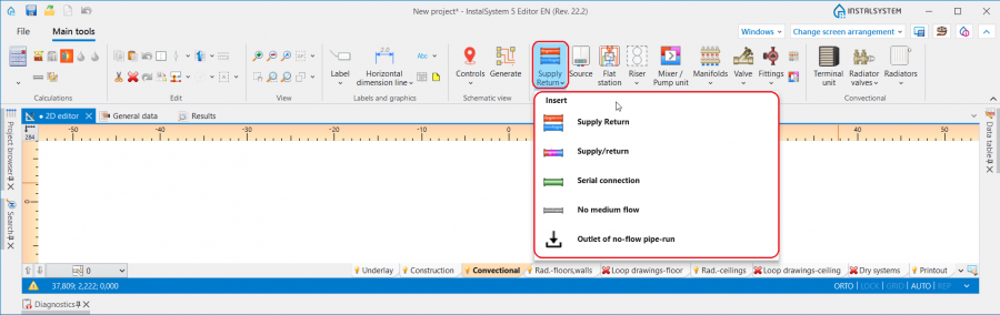
1. 管路 - 供热系统计算 或供冷系统计算. - 当勾选了给水系统计算 ,在2D编辑器 窗口,进入给水系统 编辑器,就可在主工具 选项卡, 水力分配 - 给水系统 工具栏内,看到与管路 相关的图标。

2. 管路 - 给水系统计算. - 当勾选了生活排水系统计算 , 在2D编辑器 窗口,进入室内排水 编辑器,就可在主工具 选项卡, 排水 工具栏内就可看到与管路 相关的图标。

3. 管路 - 生活排水系统计算.


应用举例
管路分割点和中点
- 一根管路 可以由多个通过中点连接的管段组成。
- 两根管路 由管路分割点,也就是通过一个接头/节点分开。
- 可以使用关联菜单和其中可用的功能在管路 上放置任意数量的附加点:插入中间点 和 插入分割点。
- 中点可以更改为分界点,反之亦然:
管路与地面以及管路与天花板之间的省缺距离
在参数表 窗口,在如下的区域中,可为每一楼层 的每种管路 设定它们与地面的省缺距离,并可为顶面辐射板的布置设定每种管路 与天花板的省缺距离:
- 对于供热系统计算 和供热系统计算 :
- ΔH管路,供 和ΔH管路, 回 - 在楼层参数中指定的管路至地面之间的距离(不适用于顶面辐射板的输配管路)。符号中的供指供水,回指回水
- ΔH管路.辐射板 - 顶面辐射板输配管路至天花板的距离
- 对于给水系统计算 :
- ΔH管路,热水 - 管路至地面的默认距离(在一般参数的楼层管理中设置) 对于管路 :热水
- ΔH管路,冷水 - 管路至地面的默认距离(在一般参数的楼层管理中设置) 对于管路 :冷水
- ΔH管路,循环 - 管路至地面的默认距离(在一般参数的楼层管理中设置) 对于管路 :循环

4. 省缺的管路距离

管道敷设距离
- 在参数表 窗口中,可以为管线对 /三根管路 指定它们之间的距离 。在管路部件插入后,程序将记住最后指定的距离,以便下次使用时再次使用该值。

5. 管线对的距离

确定 供热系统计算, 供冷系统计算 和给水系统计算管路的竖向对齐
可以在2D编辑器 和3D视图 窗口中,选择部件后显示的专用编辑器来管理管路的对齐和标高:
 - 显示管路端点的标高
 - 显示一段的标高
 - 显示管路的端点/与地面的距离
6. Display of the elevations of a 管路 in the 2D编辑器 and 3D视图 window.

InstalSystem 5 offers three methods of managing the alignment of a distribution system that allow the most convenient method to be selected to suit the individual design context. The method should be selected in the 管道标高设置 editor in the 参数表 window for the 管路:
- 自动 mode:
- Editors showing the elevation of pipe-run ends and distance from the floor are greyed out and the values presented cannot be modified.
- The value of 标高 can be modified in the 参数表 window for the 管路 and this change automatically modifies the values in all editors for the selected component.
- 手动调整局部的标高 mode:
- In the editors available in the 2D编辑器 and 3D视图 window it is possible to specify the elevation and distance from the floor of a pipe-run section.
- Based on the difference between the specified section elevations, vertical pipe-runs are automatically created.
- Editors of pipe-runs connected on one end to terminal units are greyed out and these cannot be edited.
- The 2D编辑器 and 3D视图 windows do not display editors with elevations of vertical sections of pipe-runs.

7. 管道标高设置 - 手动调整局部的标高.
- 手动调整节点的标高:
- Editors in the 2D编辑器 and 3D视图 window enable specifying the elevations and distance from the floor of the ends of a 管路 section.
- Vertical sections of pipe-runs are NOT automatically created - the entire pipe-run layout is controlled by the user.
- Editors of pipe-runs connected on one end to terminal units are greyed out and these cannot be edited.

8. 管道标高设置 - 手动调整节点的标高.


Attention! Every change of elevations and modification of 管路 layout requires running a 检查连接 operation available on the 主工具 bar in section 计算.
Determining the vertical alignment of pipe-runs - 生活排水系统计算
The elevations and gradient of a pipe-run can be managed using dedicated editors that are displayed after selecting a component in the 2D编辑器 and 3D视图 window:
 - shows the elevation of pipe-run sections, values presented in the editors correspond to the fields: 第一个节点标高 and 第二个节点标高 available in the 参数表 window of the component.
 - shows the gradient of the pipe-run and corresponds to the 实际坡度 field available in the 参数表 window of the component.
5. Display of elevations and gradient of a 管路 in the 2D编辑器 and 3D视图 window.

When laying the pipe-runs, they adopt a gradient according to the direction of flow to the sewage outlet, taking into account the settings made in the 一般参数 window on the 生活排水系统计算/ 计算标准和选项 tab:
- The default minimum gradients specified for the selected component locations are adopted. In addition, the pipe-run laying algorithm takes into account the elevation and gradient values specified by the user in the editors described above.
- The 器具排水管的连接方向控制 is taken into account:
- for the 朝向地板 setting - pipe-runs are arranged towards the terminal units with minimum gradient. If necessary, vertical pipe-runs at the terminal units are added taking into account the value specified in 排水横支管在立管上的连接点与地面完成面的距离 field,
- for the 朝向墙体 setting - pipe-runs are arranged downstream of the terminal unit with the gradients specified in the 一般参数 window, and they are then connected to the collective branch by means of a vertical pipe-run (if drawing it is necessary for the continuity of the system).

9. Alignment of pipe-runs - 生活排水系统计算.

Laying pipe-runs in a single vertical plane
- Appropriate setting of elevation values of individual types of pipe-runs in the 参数表 window for a 楼层 in sections: 供热/供冷系统 or 给水系统 and specifying the minimum value in the 距离 field in the 参数表 window of a 管线对/ Three pipe-runs, enable aligning pipe-runs in one vertical plane, e.g. in a wall one over the other.
Inclined pipe-runs
- The 管道标高设置 function enables full control over the alignment of a pipe-run, which, together with the possibility of marking points on a component, makes it possible to draw inclined pipe-runs and to design the connections of systems located on inclined attic elements.
Basic rules of connecting pipe-runs to other system components
The 主工具 bar in the 编辑 group offers three methods of automatic connecting of terminal units to the pipe-run arrangement drawn beforehand:

- 自动连接末端装置 - connects selected 管路 components and terminal units within the following scopes: 供热系统计算, 供冷系统计算 and 给水系统计算.
- 自动用活水三通连接件连接末端用水点 - connects selected 管路 components and terminal units of a water supply system in a tee joint system.
- 串联连接 - connects 顶面辐射板/毛细管网 or 墙面辐射板/毛细管 components selected beforehand using a 串联连接 type pipe-run. 更多信息,见: Designing panel (ceiling, wall) heating/cooling systems.
For all components connected to a system (e.g. 末端装置, 混水装置, 分/集水器), a horizontal pipe-run section 5cm long is drawn, followed by a bend to arrive at the defined elevation of the 管路. Exceptions from this rule:
- Connection of a 散热器 with an integrated angled valve - a horizontal pipe-run section is drawn of a length of: 与墙壁的距离 + 5cm, followed by a bend to arrive at the defined elevation of the 管路.
- Connection of a 供水水龙头 - a horizontal pipe-run section 1cm long is drawn, followed by a bend to arrive at the defined elevation of the 管路.

11. Connection of a 供水水龙头. - Connection of a 立管 - if the pipe-run connection is made directly, with no midpoints, the pipe-run elevation adopted corresponds to the actual value in accordance with the data given in the 参数表 window of the 管路.
- Connection of a 混水装置/控制回路 - the 自动连接末端装置 operation results in connecting only the points that are on the primary side of the 混水装置.

Pipe-run in auto mode
When pipe-runs have been drawn in a project in such a way that within one storey there are vertical pipe-runs (created not by inserting a 立管, but by connecting four pipe-runs or pipe-run pairs), pipe-runs to be connected to these vertical sections are subject to defined drawing rules:
- when drawing components with the Auto mode enabled, the 管路 is connected to the vertical pipe-run with its elevation retained.
- when connecting a pipe-run to pipe-runs the coordinates of which overlap, the 管路 drawn is connected to the component of the lowest elevation.

12. Connection to vertical pipe-runs.
