自动创建系统示意图:修订间差异
无编辑摘要 |
|||
| 第27行: | 第27行: | ||
==在程序中的位置== | ==在程序中的位置== | ||
用于控制示意图自动生成的组件和功能图标可在''<IS_TS id=NarzedziaGlowne/>'' 的''<IS_TS id=GraphicalEdit/>'' 窗口内的 ''<IS_TS id=ScopeInstalacjeKonwekcyjneShort/>'', ''<IS_TS id=ScopeInstalacjePodlogoweIScienneShort/>'' ,''<IS_TS id=ScopeInstalacjeSufitoweShort/>'' 编辑器内找到。<br/>[[File:TB-schematic-view-location.png|900 px|left|thumb|1. ''<IS_TS id=SchematicView/>'']]<br clear="all"/> | |||
The generated ''<IS_TS id=ArkuszTypuRozwinięcie/>'' components are at the bottom of the sheet list.<br/>[[File:TB-schematic-view-location-schematic2.png|900 px|left|thumb|2. ''<IS_TS id=ArkuszTypuRozwinięcie/>'']]<br clear="all"/> | The generated ''<IS_TS id=ArkuszTypuRozwinięcie/>'' components are at the bottom of the sheet list.<br/>[[File:TB-schematic-view-location-schematic2.png|900 px|left|thumb|2. ''<IS_TS id=ArkuszTypuRozwinięcie/>'']]<br clear="all"/> | ||
2020年2月4日 (二) 12:27的版本
| 产品 | InstalSystem 5 |
| 文章类型 | 功能和工具 |
| 版本的最新内容 | REVISION Rev. 17.1 |
说明
本文介绍了基于应用: 供热系统 或 应用: 供冷系统 类型的系统安装模型自动创建示意图的方法。自动创建的示意图还具有手动编辑、插入配件和随时再重新生成视图的选项。
系统安装示意图通过在2D编辑器中使用起始点 (供热供冷系统) 来生成。
本功能目前正在开发中,已包含在BETA版本中
在程序中的位置
用于控制示意图自动生成的组件和功能图标可在主工具 的2D编辑器 窗口内的 对流, 地面/墙面辐射 ,顶面辐射 编辑器内找到。

The generated 工作表类型: 示意图 components are at the bottom of the sheet list.

Examples of use
检查连接
Checking the correctness of connections using the 检查连接 operation or by pressing Shift+F2 is necessary for the proper generation of the schematic view. The project file can include messages on error relevance, but these messages cannot relate to connection errors.
Presentation of the basic components and functions for controlling automatic generation of schematic views
起始点 (供热供冷系统)
This is the starting point in the installation from which the schematic view is generated. It has to be assigned a unique symbol. Many 起始点 (供热供冷系统) components can be inserted, and each of them generates a separate 工作表类型: 示意图 
The 起始点 (供热供冷系统) can be placed on:
- 源
- 立管
- 管线对
- 分/集水器
- 户用换热机组
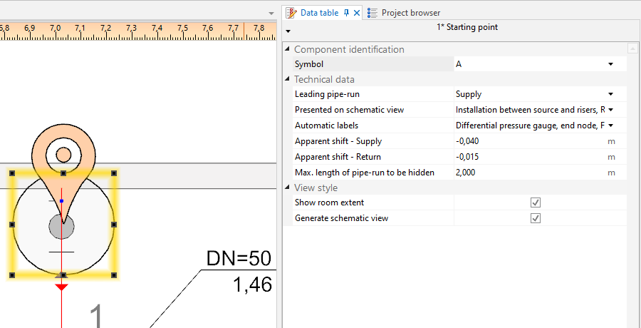
3. 起始点 (供热供冷系统)

- 领管路
Indication of the pipe-run which has a priority when generating a schematic view. This is important when generating an asymmetrical installation (supply and return pipe-runs arranged along different routes). All junctions (tees, crosspieces) are also marked on leading pipe-runs.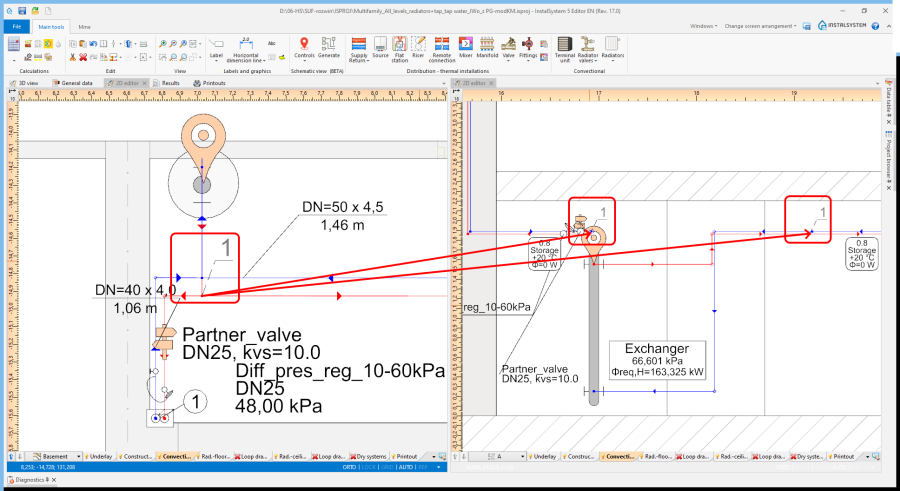
4. Junction (tee)
The scope can be reduced:- 源和立管之间的装置 - generates the schematic view from the indicated point to risers, excluding the risers
- 立管 - generates the schematic view from the indicated point to risers, including the risers
- 立管后面的装置 - generates the schematic view from the indicated point beyond the risers to terminal units. If an installation includes stations, the schematic view is terminated at the station, if the installation includes manifolds, the schematic view is terminated at the manifold.
- 户用换热站后面的装置 - generates the schematic view from the indicated point to the station including the installation beyond the station (checkbox 立管后面的装置 must be checked)
- 分集水器后面的装置 - generates the schematic view beyond the manifolds (checkbox 立管后面的装置 must be checked)
- Control over automatic labelling.
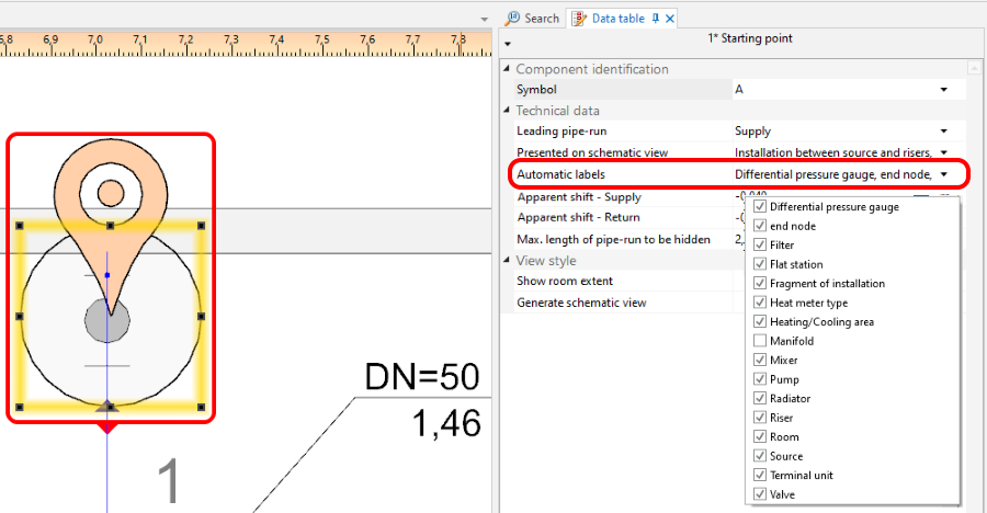
5. Schematic view - labels control - 标高的位移量
Enables display in the schematic view of pipe-runs that are on the same level (elevation). Does not affect the elevation of the pipe-run in the model.- Positive value - this value is added to the elevation of the supply pipe-run in the schematic view.
- Negative value - this value is subtracted from the elevation of the supply pipe-run in the schematic view.
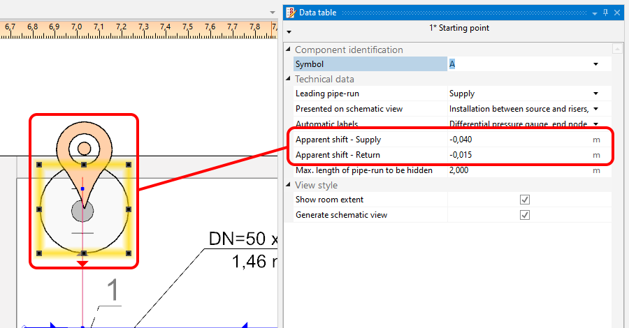
6. 标高的位移量 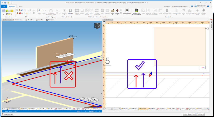
7. 标高的位移量 - supply and return
- 显示所有房间
Marked rooms and their labels.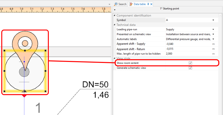
8. 显示所有房间 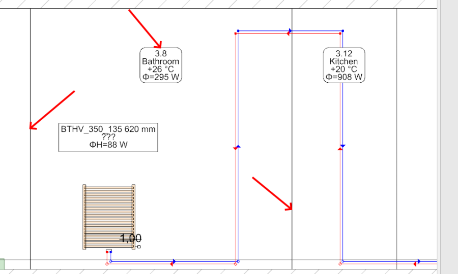
9. 显示所有房间 - room marked in the schematic view - 创建示意图
Unchecking this option disables the generation of the schematic view during subsequent generations, e.g. new settings for the automatic schematic view control functions will not be taken into account. However, disabling this option does not affect installation components. The installation components are refreshed automatically, i.e. the number of installation components in the model always corresponds to the number of installation components in the schematic view. If this option is disabled, a padlock icon is shown in the sheet selection list .
.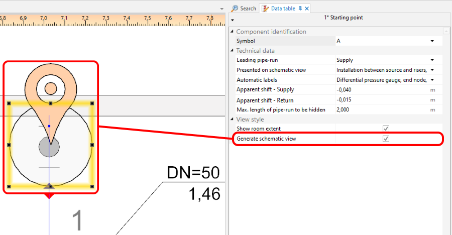
10. 创建示意图


控制点
Enables controlling the direction of generation of individual pipe feeds on the schematic view and modification of the leading route. It must be placed on the leading pipe-run. The control point changes the course of the schematic view starting from the junction beyond which it was inserted. Many 控制点 components can be inserted and they can be placed in a 工作表类型: 示意图 or a 工作表类型: 平面图.

- 方向.
Specifies, for instance, whether a part of an installation (e.g.: 立管) is to be treated as placed to the right or to the left of the 源. Similarly, one can decide whether a part of the installation is to the right or to the left of a 立管. The video shows how two risers are moved in the schematic view to the left of the source.
- 示意图中有断点.
Enables modifying the leading route in the schematic view. The video shows how the leading route is changed in such a way that the critical route is presented as the first one.
终点
The schematic view of the part of installation that is beyond the 终点 is not generated. This part of installation is represented by a 系统部件. The 终点 must have a unique symbol assigned.
The video shows how a riser is removed from the schematic view.
Parts of installation that are not subject to automatic generation of schematic views
- Installations with ceiling panels.
- Installations with wall panels.
These parts are automatically terminated with a 系统部件.
Manual editing and configuring
- Inserting independent components.
The following components can be placed in a 工作表类型: 示意图:- additional labels (e.g.: pipe-run labels). The positions of the inserted labels can also be changed - these positions are maintained after the schematic view is regenerated,
- valves,
- fittings placed on pipe-runs,
- radiator fittings.
Additional information
- Project file created with InstalSystem 4 which includes a 工作表类型: 示意图 loaded into InstalSystem 5.
Such a sheet is not converted into a 工作表类型: 示意图 of InstalSystem 5 and it is removed when loading - appropriate diagnostic message is displayed.