===Opening a project file and managing projects===
===打开一个项目文件和项目管理===
====Creating a new project or opening an existing project====
====创建一新文件或打开一现有的文件====
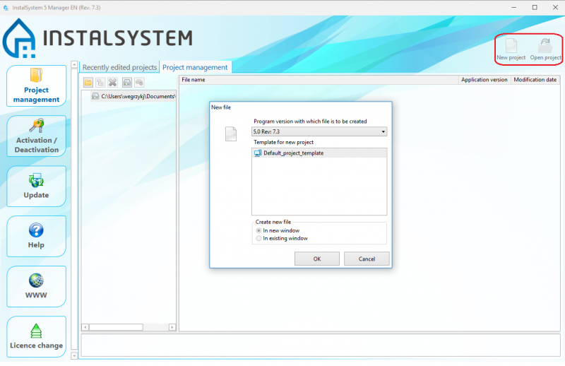
# '''New file''' - when opening a new file you can indicate a template to be used in the project and select one of the downloaded program revisions to work with the file. We recommend using the most recent revision of the program.
# '''Existing file''' - when opening an existing project file you can select the program revision to further process the file. This enables working with the project using the program revision under which the project was first created.<br/>'''InstalSystem 5''' also reads files created with [http://en.help.instalsoft.com/InstalSystem_4 InstalSystem 4].<br/>[[File:New-file.png|900 px|left|thumb|7. New file]]<br clear="all"/>
====Managing project files and additional files====
====管理项目文件和其它文件====
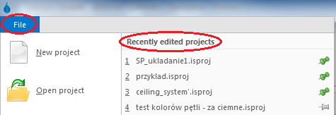
# '''Recently edited projects''' - this list is created automatically and it facilitates accessing projects that were recently edited, irrespective of their location. It is accessible both from the ''Manager'': <br/>[[File:Recently-edited-projectd.png|900px|left|thumb|8. Recently edited projects]]<br clear="all"/> as well as in the File menu of the ''InstalSystem Editor'' window.<br/>[[File:Recently-edited-projects-file.png|900px|left|thumb|9. Recently edited projects]]<br clear="all"/> There is an option to select projects that will always appear on the top of the list no matter when they were processed. This is done using '''tacks''' - just click the tack [[File:Pin-off.png|32 px]] beside the selected project and it will move to the top of the list and will remain there permanently [[File:Pin-on.png|32 px]].
# '''最近编辑的文件''' - 这个列表是自动创建的,它有利于访问最近编辑的项目,不管它们的位置如何,都可通过下述方式进行访问: ''Manager'': <br/>[[File:Recently-edited-projectd.png|900px|left|thumb|8. 最近编辑的项目]]<br clear="all"/> 以及as well as in the File menu of the ''InstalSystem Editor'' window.<br/>[[File:Recently-edited-projects-file.png|900px|left|thumb|9. Recently edited projects]]<br clear="all"/> There is an option to select projects that will always appear on the top of the list no matter when they were processed. This is done using '''tacks''' - just click the tack [[File:Pin-off.png|32 px]] beside the selected project and it will move to the top of the list and will remain there permanently [[File:Pin-on.png|32 px]].
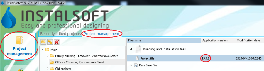
# '''Project management''' - During program installation it's possible to set the default location for projects. This location and all its subfolders and files it contains are then accessible from the ''Project management'' tab in the ''InstalSystem Manager'' window. It is advisable to create a separate subfolder for every project (designed structure/system) and save there the individual '''InstalSystem''' versions of the project (.isproj extension) and other additional files, e.g. base construction drawing files. Additional advantage is that the files in the .isproj format are displayed using that software version with which the project was developed. <br/>[[File:Project management.png|900px|left|thumb|10. Project management]]<br clear="all"/>
# '''Project management''' - During program installation it's possible to set the default location for projects. This location and all its subfolders and files it contains are then accessible from the ''Project management'' tab in the ''InstalSystem Manager'' window. It is advisable to create a separate subfolder for every project (designed structure/system) and save there the individual '''InstalSystem''' versions of the project (.isproj extension) and other additional files, e.g. base construction drawing files. Additional advantage is that the files in the .isproj format are displayed using that software version with which the project was developed. <br/>[[File:Project management.png|900px|left|thumb|10. Project management]]<br clear="all"/>
最近编辑的文件 - 这个列表是自动创建的,它有利于访问最近编辑的项目,不管它们的位置如何,都可通过下述方式进行访问: Manager: 8. 最近编辑的项目 以及as well as in the File menu of the InstalSystem Editor window. 9. Recently edited projects There is an option to select projects that will always appear on the top of the list no matter when they were processed. This is done using tacks - just click the tack beside the selected project and it will move to the top of the list and will remain there permanently .
Project management - During program installation it's possible to set the default location for projects. This location and all its subfolders and files it contains are then accessible from the Project management tab in the InstalSystem Manager window. It is advisable to create a separate subfolder for every project (designed structure/system) and save there the individual InstalSystem versions of the project (.isproj extension) and other additional files, e.g. base construction drawing files. Additional advantage is that the files in the .isproj format are displayed using that software version with which the project was developed. 10. Project management
Working with the project
General data
In the first stage of working with the project general data are set and default settings, which are used throughout the project, are verified. These data can be modified at any stage of project development. The General data window is accessible in the list of windows located on the toolbar. Detailed information on the essential scope of General data that should be edited depending on the type of system designed or calculation conducted is given in sections describing the corresponding applications of the software package - see:SOFTWARE APPLICATIONS.
11. General data
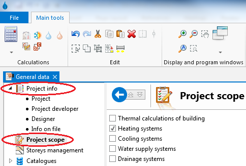
Project info and project scope - enable appending information on the project and selecting proper scope for the project being developed. 12. Project info and project scope
Catalogues - the catalogues available in the program are in the form of non-editable files with data on components that may be used when designing a system. A special type of catalogues are climatic data. Data stored in the catalogues save the user from entering numerous detailed data of the components used in the design. It suffices to indicate the product or system to be used in the project, and the program will read all the necessary details from the catalogue. At this point in general data a set of catalogues can be defined for the project. Products from this catalogue will be available when editing a system or when selecting components and conducting calculations. Depending on the software package configuration, various types and various range of catalogues will be available. Catalogues can contain data on generic components or on components from a specified manufacturer. 13. Catalogues
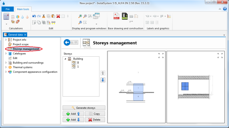
Building data - enable defining basic data on a building in the context of systems being designed. Building and surroundings covers information on the location of the building and on default building structure components data, e.g. required heating or cooling output indexes. 14. Building and surroundings Storeys enable defining or modifying the structure of the building (number of storeys and basic data thereon). For each storey a separate drawing sheet is automatically created to enable working with the plan of that storey. 15. Storeys management
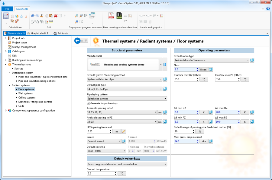
Default data of systems designed - these data are transferred to all system components that have the default (computer symbol) indicated in their specific fields. Newly inserted components have this status. The default value can be changed at any time - the individual components can have their data either specified directly by the user or the default setting can be restored. The General data are accessible in the General data window in the form of several sets assigned to individual sections of the project, e.g. Thermal systems. 16. Default data for floor heating systems
Component appearance configuration and editing parameters configuration - appearance of components (e.g. in terms of colour or scale) and some editing parameter can be configured for each project separately. This enables better adapting the appearance of drawings and manner of work to the individual requirements of the project being developed. If the user wishes to apply these modified settings to other projects, the file with those modified settings can be saved as a new template - see:point 3. Template files in Configuration 17. Component appearance
Basic components of graphic editing environment
The basic locations where project data are edited are the Graphical edit and Data table windows. How to open or change the location of these windows within the screen is described in: Configuration, 2. point. The most important functions are accessible through the Main tools bar and through the pop-up menu displayed after pressing the right mouse button. The pop-up menu is context-dependent - its availability and content depend on the location within the screen or object being indicated.
18. Basic of graphic editing
Graphical edit - the graphical edit window enables making all editing operations on the components that make up the building structure or the systems under design. It is possible to use two separate graphical edit windows at the same time, each of them displaying different portion of the project. The most important components of this window are the following:
Drawing sheets - the graphical edit window displays one, currently selected, drawing sheet. A project can contain many drawing sheets, each of them usually assigned to a different building storey - see:SETTING UP THE BUILDING STRUCTURE. The active drawing sheet can be changed through the choice list in the upper left corner of the edit window 文件:Drawing-sheets-png.png
Edit tabs - these are layers of the drawing sheet. Depending on the active tab, specific components of the project are editable. Some components can be edited on more than one tab. The contents of the Main tools bar also depends on the active tab. Whether a tab (and consequently drawing components assigned to it) is displayed or not is configurable. The options available are displayed upon right clicking the tab label. The symbol placed to the left of the tab label indicates the current setting of its show/hide status
Operating modes - apply to editing of building structure or of any system. The modes can be enabled/disabled in the lower right corner of the graphical edit window 文件:Auto-orto.png
ORTO - The ORTO mode enables maintaining right angle when editing which allows inserting lines positioned at a right angle to the axes of the coordinate system. Pressing and holding the Ctrl key temporarily enables/disables the ORTO mode, which is very convenient when doing some editing operations.
GRID - The GRID mode supports manual arrangement of pipe feeds and drawing a loop within a HCZ.
AUTO - The AUTO mode activates automatic snapping, that is attracting components to points of possible connection or performing other automatic operations during editing, depending on the type of inserted or edited component and on its surroundings. Pressing and holding the Shift key temporarily enables/disables the AUTO mode, which is very convenient when doing some editing operations.
The ORTO and AUTO mode operating parameters setup window - enables adjusting these modes to individual requirements. The window can be displayed in the lower right corner of the graphical edit window.
The entire project can be previewed by pressing a button in the lower right corner of the Graphical edit window.
A button in the lower left corner of the Graphical edit window enables changing the plan display scale.
Data table - data of the currently selected component or object are available in the Data table. If multiple components of the same type are selected, then data fields common to all these components will be displayed in the Data table, enabling thereby simultaneous changing of selected data of multiple components.
Main tools - toolbar with the most important tools, functions and component icons used for editing. The contents of the toolbar, whether its complete sections are displayed or hidden and whether the individual icons are active or inactive depends on the context - active window, and within the Graphical edit window - active tab. When the mouse cursor is positioned over a selected icon, a hint is displayed. This helps familiarize with the contents of the toolbar.
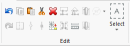
The Edit section provides general editing functions and a multi-level undo/redo functionality.
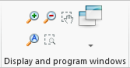
The Display and program windows section provides tools for manipulating the project display in the Graphical edit window.
Zoom out and Zoom in commands for the project display, in addition to the icons in this section, are also accessible by means of the mouse wheel.
Move the project display, in addition to the icon, is also accessible by pressing and rotating the mouse wheel.
Show all in addition to the icon, is also accessible by pressing the F5 key.
Setting up the building structure
The building structure forms a base for creating the system design. The building may consist of several storeys. A separate drawing sheet in the form of a plan is created automatically for every storey. In that sheet components of the building structure and of the system under design within that storey can be edited. The individual domains of the project are edited on separate tabs (layers), whereas the entire building and all of its systems designed form one consistent and integrated project. There are several methods of preparing the building structure for the design. Selection of the method depends on the available source data on the structure and plans of the storeys and on the scope of the design to be developed.
Import complete building structure - the best solution is to import data from a gbXML file. To make such an import the Base tab should be selected and the building icon, on the toolbar should be clicked to run the import function. After indicating the file to be imported, the process proceeds automatically. When importing from a gbXML file, both the structure of the storey referred to when discussing general data, as well as building components that form the plans of the individual storeys are imported.
Import plan views of individual storeys - may significantly improve work efficiency when files with drawings of the individual storeys of the building are available. In such case first the building structure must be defined in the Storeys section of General data. Then the plan views of the individual storeys should be imported from files in one of the supported formats, for instance: DWG, DXF, PDF, BMP, JPG and many other. Particularly useful is the import of the base drawing in the DWG format, as this makes the snapping function available when editing the structure. To import the base drawing the Base tab should be selected and then the "Drawing/base" component inserted into the project. Upon inserting that component, its data available in the Data table should be accessed and the file to be imported should be indicated in the Graphic file field. If printed plan view drawings are available, these can be scanned or photographed and the obtained file imported. 19. Import base The scale of the imported drawing should be specified by selecting the appropriate unit in the "Unit of measure in drawing" field in the Data table. After importing and scaling of all storeys the alignment of the drawings should be verified. To correct the alignment the Reference point component may be used. Then the required building structure components should be placed on the Structure tab, as described below in the Manual structure edit section, whereas the loaded base drawings form a background which facilitates structure editing.
Manual structure edit - the program enables drawing the required components of the building structure, rooms in particular, which will form basis for further design. Also in this case the building structure must first be defined in the Storeys section of General data. To define the area occupied by a room the Room function should be selected on the toolbar in the Structure tab. In this manner the areas of all rooms can be defined. 20. Room
Verification of the correctness of building structure
After defining the structure of the building it is advisable to verify the data that have been entered using the 3D view. The 3D view window is accessible in the list of windows located on the toolbar. The 3D view can be rotated in every direction which enables data verification using views from different sides and at different angles. The 3D view is controlled by means of a cube in the upper right corner of this window or by button ctrl and middle mouse button ("scroll") combination.
21. Building structure
Installation edit
The basic way to enter data of the system under design in InstalSystem 5 is graphical editing. Designing consists in placing objects (installation components) in the drawing and making appropriate connections between them. Work is done on plan views of the building storeys. The installation thus created can then be modified in any way, its fragments can be copied, and other operations can be made on it.
The software package offers a number of functions that support graphical editing, reduce the scope and time of necessary manual operations at this stage of design. Some components may be inserted or generated automatically. It is also possible to insert and edit groups of components.
There is a range of predefined graphical objects that can be used in the project. Examples: Project table, where designer data can be entered and which can be used when printing the project, or interactive elements, such as Manifold table and Component labels. Upon assigning them to defined system components, they will automatically display current data of these components.
It is particularly straightforward and problem-free to make all kinds of modifications to the project - the ergonomics and ease of calculation of the modified design is one of the biggest advantages of the working environment of InstalSystem 5. 文件:Graphical-edit.png22. Installation edit
Detailed information on Installation edit, in the context of the type of system being designed or calculations performed is given in the descriptions of program applications - see:SOFTWARE APPLICATIONS.
Verification of the correctness of installation structure
Before detailed component data are appended it is a good idea to check the structure of the system and component connections. Corrections made to the structure may cause changes or even removal of some of the components, then the time spent on entering data would be lost. The following tools are available:
The tool that enables checking connections between system components in the project is the Check connections function, which is also available through the keyboard shortcut Shift+F2. 23. "Check connections" function
The tool that enables visual verification of the installation structure is, as is the case with building structure verification, the 3D view. The 3D view can be enabled permanently, which allows verifying system correctness continuously during editing. In this case it is particularly advantageous to work using two display monitors simultaneously. Note, however, that using 3D view slows down the program. When working on a slow computer or working with a large project, it is better to enable 3D view only to verify the status of the project, and to do the design work without opening the 3D view window. 文件:Installation-project.png24. Installation structure
Component data edit
Every component in the project has its set of data. Editing these data is possible in the Data table after marking that component. This applies to components of the building structure, components of all systems under design, and other components that are objects of the program, such as the "Graphical file" mentioned when discussing the import of storey plan views or the "Print layout". The Data table can be toggled on/off by selecting it in the Window menu on the toolbar.
A significant portion of the data of new components placed in the drawing is appended automatically. This highly facilitates work on the project. The range of automatically appended data differs depending on the type of component and on other factors.
The basic mechanism in this area is propagation of General data
Some data are established based on component location and size / shape of component placed in the drawing
Many detailed data of components that are associated with catalogue data and have a specified catalogue type are read from the catalogue.
Any default data can be overwritten with other data at any time. Information on whether the current value is derived from the "General data" or is another type of default data, or whether it is a user-defined value, is in the form of an icon placed to the right of the data field in the Data table. Clicking this symbol changes the data status. In particular it enables reverting to the Default status.
A Computer symbol indicates a default value
A Pencil symbol indicates a user-specified value
Data of any component can be entered or modified at any moment when working with the project.
Component data can be edited right after placing the component in the project, and this is recommended for some components. This particularly applies to these components that do not depend on other drawing components and the number of which in the project is low.
In the case of components the number of which is high it is advisable to edit their data at one stage to take advantage of group editing. To this end it is necessary to press and hold the Ctrl key and click every component to be marked. After marking multiple components, the data fields common to all those marked components will be accessible in the Data table, and every change made to selected data will modify that data for all marked components. Therefore it is very useful to conduct group editing of data of components of the same type, e.g. of many rooms.
Calculations and diagnostics
Calculations include all operations necessary to obtain complete results: data propagation, component sizing, engineering calculations and automatic graphical editing. All data that have an effect on the selected scope of the project are taken into consideration: general data, building data, drawings of the system under design, parameters of components used to construct the system taken from catalogues. This means that the program automatically provides high level of completeness and consistency of data and results. This approach greatly facilitates reverting to any of the previous stages of editing - after changing selected data, calculations can be conducted again to obtain complete and current results. Ease of reverting provides great comfort and speed of work in the context of calculating various design options, taking into account the changing requirements of the project developer or changes in the structure of the building introduced during the design of the installation.
Starting calculations - the Calculation section of the Main tools bar contains tools that enable starting and managing calculations. Calculations can be made for the entire project or for selected scopes.
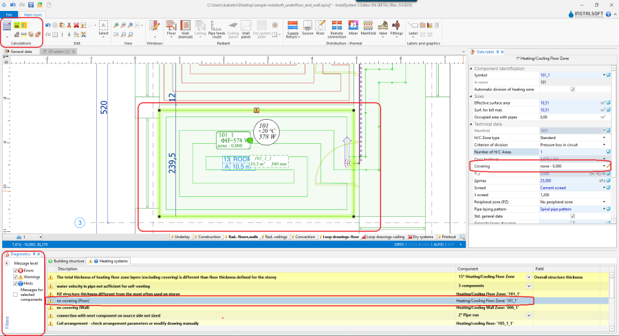
Diagnostics and error list - at the start data completeness and correctness is verified. Significant errors in the data result in error messages and halted calculations. If there are no significant errors, calculations are completed and the error list is filled with diagnostic messages. These messages provide information on errors that do not halt calculations and warnings and hints regarding the course of calculations and obtained results. The Errors window is accessible through the Display and program windows menu. Initially all messages are displayed in bold font. Double clicking on a message enables finding the components or data referred to in the message in all open windows, for instance: Graphical edit, Data table, Calculation results. After the first search the message is displayed in normal font, meaning that it has been "checked". The pop-up menu available after selecting the message and right clicking allows viewing all components which encountered a similar problem. The range of displayed groups of messages can be controlled using the Filters function.
Errors - messages of highest importance, displayed in uppercase. Critical errors halt calculations and must be eliminated. There are also errors that do not halt calculations, but nevertheless they must be closely analysed and rectified.
Warnings - messages of lesser importance than errors, displayed in lowercase letters and they do not block further calculations. Warnings are usually associated with data or results that are presumably incorrect, therefore it is always advisable to read the displayed warnings.
Hints - messages intended to remind of or draw attention to some data or results.
Messages for selected components. 26. Error list
Calculation results - in the InstalSystem the entire project may have a "calculated" status or a "not calculated" status. First calculation run changes the project status into "calculated". Calculations have an effect on the information displayed in many windows of the application. Importantly, changes made in data after first calculations do not cause deletion of results, results of the last calculations are available. An appropriate message warns of such status of the project. Results in the Label are crossed out if the project has changed. The most important result components:
Tables and lists available in the Calculation results window. 文件:Calculation-results.png27. Calculation results
Components displayed in the project drawing in the Graphical edit window, for instance results displayed in component labels or graphical components drawn or modified during automatic edit operations.
Information available after completing calculations, but not displayed permanently, for instance detailed results available in Graphical edit in Hints appearing in the case of most components when cursor is placed over it. 文件:Pipe-run-results-hint.png28. Pipe-run hint
Detailed information on calculations and results in the context of the various types of systems is given in the descriptions of software applications - see:SOFTWARE APPLICATIONS
Preparation of drawings for export/printing
After making all the required changes to the project and completing calculations, project components that complement information provided in printouts can be entered into the project. These components have an informative nature, and they do not affect calculations. It is advisable to place them in the project at this stage only, as the iterative work with the project at the earlier stages may require modification also in this respect. Including them at the final stage of work may prove most efficient. Detailed information on the available types of components in the context of the various types of installations is given in the descriptions of software applications - see:SOFTWARE APPLICATIONS.
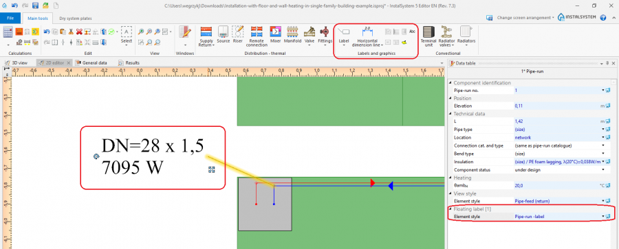
Example Component labels accessible through Main tool bar in the Labels and graphics section. A label is placed by selecting the appropriate icon in the toolbar and clicking the component to which the label is to be assigned. Upon marking in the drawing a component with a label, the label style can be selected in the Data table. 29. Component label The user can configure the label style - see section 5 Component appearance configuration and editing parameters configuration in General data. The user can create and save his/her own label styles of various configuration.
Export/print results and drawings
Result tables and drawings can readily be printed or exported in one of the many available formats.
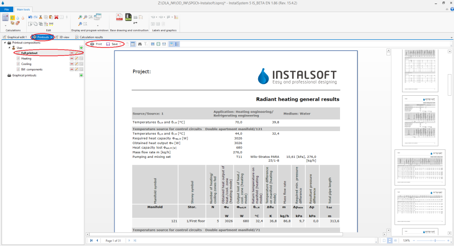
Print tables and lists - to print or export it is necessary to open the Printouts window. The tree displayed on the left side shows the available predefined printout compositions. The number and types of predefined proposals depend on the software version used. A composition can be selected and its content viewed. Then it is only necessary to select Print to obtain a printout or Save and, after selecting the target file format, export the results to this format. It is also possible to create and save user-defined printout compositions. These compositions, in addition to the predefined compositions, are then also available in other projects. 30. Print tables and lists
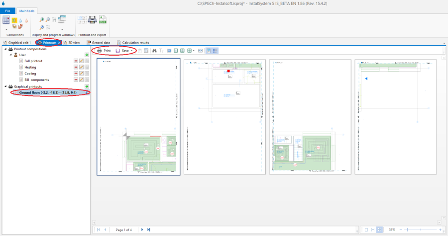
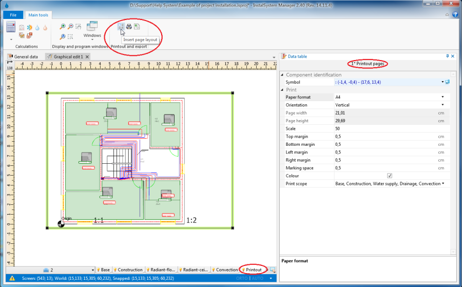
Print drawings - drawings are also printed and exported using the Printouts window. The tree displayed on the left side, below the table printout compositions, shows the graphical printouts defined for the project. The user can define many different layouts of graphical printout. For the defined layout, printing can be effected a number of times, e.g. after every project modification. The range of pages, its setup, style and other parameters are saved. This enables defining various printouts, e.g. one for exporting to a PDF file, another for sending to a printer, yet another for sending to a plotter. 31. Print drawings To set up a graphical printout layout it is necessary to:
Select Printouts tab in the Graphical editor window
At Insetr page layout tool is available in the Printout and export section of the toolbar. This tool enables placing a Printout pages component in the drawing. To each Printout pages component placed in the drawing corresponds a separate graphical printout item in the Printouts window
The Printout pages component can be configured in the data table - a name should be assigned to it, its size, page layout and other style components can be modified
In the graphical edit area the outline of this component can be dragged by the mouse to an appropriate location in the project drawing. Its size can also be changed by dragging one of the corners, whereas the size is always a multiple of full pages. This way the area of the project to be printed can be marked. 32. Printout configuration



 beside the selected project and it will move to the top of the list and will remain there permanently
  .
.








 , on the toolbar should be clicked to run the import function. After indicating the file to be imported, the process proceeds automatically. When importing from a gbXML file, both the structure of the storey referred to when discussing general data, as well as building components that form the plans of the individual storeys are imported.
 component may be used. Then the required building structure components should be placed on the Structure tab, as described below in the Manual structure edit section, whereas the loaded base drawings form a background which facilitates structure editing.


 - messages of highest importance, displayed in uppercase. Critical errors halt calculations and must be eliminated. There are also errors that do not halt calculations, but nevertheless they must be closely analysed and rectified.
 - messages of lesser importance than errors, displayed in lowercase letters and they do not block further calculations. Warnings are usually associated with data or results that are presumably incorrect, therefore it is always advisable to read the displayed warnings.
 - messages intended to remind of or draw attention to some data or results.