机械通风系统的设计:修订间差异
(建立内容为“{{Article table |commercial_product1=InstalSystem 5 |p2 =<!--gdy jest kolejny produkt handlowy, zamienić na->"produkt_handlowy2="--> |p3…”的新页面) |
无编辑摘要 |
||
| 第5行: | 第5行: | ||
|p4 =<!--gdy jest kolejny produkt handlowy, zamienić na->"produkt_handlowy3="--> | |p4 =<!--gdy jest kolejny produkt handlowy, zamienić na->"produkt_handlowy3="--> | ||
|category1 =InstalSystem 5#Designing lessons | |category1 =InstalSystem 5#Designing lessons | ||
|category_name1 = | |category_name1 =设计课程 | ||
|c2 =<!--Jest kategoria -> zamienić na: "category2=" i uzupełnić link do sekcji kategorii na stronie głównej produktu--> | |c2 =<!--Jest kategoria -> zamienić na: "category2=" i uzupełnić link do sekcji kategorii na stronie głównej produktu--> | ||
|category_name2 =<!--podać nazwę kategorii "ZASTOSOWANIE"/"FUNKCJONALNOŚĆ"/...--> | |category_name2 =<!--podać nazwę kategorii "ZASTOSOWANIE"/"FUNKCJONALNOŚĆ"/...--> | ||
| 第19行: | 第19行: | ||
This article presents the basic design path for the ''<IS_TS id=InstalacjeWentylacyjne/>'' for residential buildings based on off-the-shelf components. | This article presents the basic design path for the ''<IS_TS id=InstalacjeWentylacyjne/>'' for residential buildings based on off-the-shelf components. | ||
== | ==模块和程序的配置== | ||
'''InstalSystem 5''' | '''InstalSystem 5''' 需带有如下模块: | ||
*'''''<IS_TS id=PH_IS5_VENT/>'''''. | *'''''<IS_TS id=PH_IS5_VENT/>'''''. | ||
== | ==项目文件== | ||
The project file used in this lesson: [[Mechanical ventilation installation in residential building (example for the lesson)]]. | The project file used in this lesson: [[Mechanical ventilation installation in residential building (example for the lesson)]]. | ||
2024年8月16日 (五) 13:56的版本
| 产品 | InstalSystem 5 |
| 文章类型 | 设计课程 |
| 版本的最新内容 | 2024-07-29 |
Scope of lesson
This article presents the basic design path for the 通风系统计算 for residential buildings based on off-the-shelf components.
模块和程序的配置
InstalSystem 5 需带有如下模块:
- .
项目文件
The project file used in this lesson: Mechanical ventilation installation in residential building (example for the lesson).
Initial state
The project contains complete default data configured in the template file. The building structure has been elaborated on the basis of DWG layouts.
Steps to perform
Opening the project file
- When creating a new design, select from the list the template that contains the default data for the ventilation system or,
- Upload project file with existing building structure - minimum content is correct ordinates, slab thicknesses and manually created 房间.
Editing the general project data
Fill in the default data in the 一般参数 window:
- 项目范围 - determine project scope: 通风系统计算.

1. 项目范围. - 目录 – select and move necessary catalogues to the 项目可用的产品目录 table. To speed up the selection, the filters can be used. 更多信息,见: Using catalogues and catalogues data in the project.
- General data editing:
- 楼层管理:
- Create the appropriate number of 楼层 / sub-levels (by interpreting from IFC or manually);
- Set storey data:
- ΔH通风, 刚性, 上板 - 刚性风管轴线与上方楼板的默认距离;
- ΔH通风, 柔性, 上板 - 柔性风管轴线与上方楼板的默认距离;
- ΔH通风, 墙送 - 墙面送风口与吊顶的默认距离;
- ΔH通风, 墙回 - 墙面回风口与吊顶的默认距离;
- ΔH通风, 顶送 - 顶面送风口与吊顶的默认距离;
- ΔH通风, 顶回 - 顶面回风口与吊顶的默认距离;
- ΔH通风, 地送 - 地面送风口与地面的默认距离;
- ΔH通风, 地回 - 地面回风口与地面的默认距离.
- (Optionally) 房间参数 - for each/selected 房间类型, used in the project, set the values of:
- 排风量 (V回), 送风量 (V送) or 最小通风换气次数 (n最小);
- 楼层管理:


- 通风系统计算 / 默认类型和参数 – append default types:
- 默认的管材类型和绝热材料: 刚性风管;
- 默认的管材类型和绝热材料: 柔性风管;
- 默认类型: 其它部件:
- 空气处理装置 / 热回收装置,
- 分风箱 / 集风箱,
- 墙面送风口 / 墙面回风口, 顶面送风口 / 顶面回风口, 地面送风口 / 地面回风口;
- 热回收效率: 根据目录参数, 根据热损失参数 or 用户指定;
- (Optionally) control and adjustment of the default value of V最大, m/s in the specified locations of the installation.
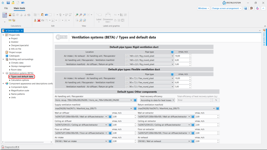
3. 默认类型和参数.
- 通风系统计算 / 计算选项:
- Select the 通风量的确定方法;
- (Optionally) enable the function 检查每人的最小新风量;
- (Optionally) improve the value of θ室外 - 室外设计温度 taken by the 室外取风口 unit.

4. 计算选项.
- 通风系统计算 / 默认类型和参数 – append default types:


Editing on the drawings
Editing the data
Set or modify the values of 排风量 (V回), 送风量 (V送) or 最小通风换气次数 (n最小) for each particular 房间 in the 参数表 in the 建筑 project scope.

Editing the installation
Carry out inserting and graphic editing operations using the 捕捉 and 定向线 modes.
- Select editing scope 通风.
- Insert 通风 elements:
- 热回收装置,
- 分风箱 and 集风箱;

6. Insert 热回收装置 and 分风箱.
- Insert 通风 terminals and indicate the 旋转角度, if necessary:
- 室外取风口,
- 室外排风口,
- 新风散流器(格栅、送风散流器),
- 回风口(室内吸风);

7. Insert 通风 terminals and indicate the 旋转角度.
- Insert 立管;
- Connect installation elements using 刚性风管 or 柔性风管.


Editing the element data
In the case of necessity modify the 通风 elements data in the 参数表 window, in particular:
- 类型 of the 通风 terminal;
- V送 / V回 for the 通风 terminal;
- 距天花板或楼板的距离 / 标高 for the 热回收装置;
- 距天花板或楼板的距离 / 标高 for the 分风箱 and 集风箱;
- 距天花板或楼板的距离 / 标高 for the 风管;
- 管材类型 for the 风管.
Verifying the correctness of the installation structure.
- Verify the correctness of the connections of the installation components using the 检查连接 function (Shortcut: Shift + F2);
- Verify the correctness of the installation structure using the 3D视图;
- Adjust the layout of the 风管 according to external factors, e.g. passages through walls, overlaps with other installations.
Running the calculations
- Start the calculation of the 通风系统计算 by clicking
 in the 计算 section of the toolbar;
 - Сheck messages the 诊断 window;
- In the case of necessity verify and adjust the installation, for example:
- increase the Diameters / 尺寸 of the 风管, if 超过最大空气流速(%s m/s>%s m/s) in the duct;
- increase 尺寸 of the 送风口 / Air extractor or add more 风管 and 送风口 / Air extractor, if 超过最大空气流速(%s m/s>%s m/s) in the 通风 terminal;
- correct the values of V送 and V回, in the case of 送排风量不平衡(ΣV送 =%s m3/h,ΣV回) = %s m3/h) .
Verification of results
- After calculations, the system layout should be verified visually by means of the 3D视图;
- If the calculations end with at least one error, the layout may be unreliable;
- The data of each 通风 element can be verified directly in the drawings.

8. Visual verification in the 3D视图 window. - Other forms of presentation of calculation results are: component labels and tables of results 更多信息,见: Presentation of the calculations result.

9. 结果 - 通风.


Preparing drawings for export/printing
- To have the results for 通风 installation elements included in the printout of a drawing, appropriate labels must be inserted 更多信息,见: Preparation of drawings for export / printing.
- Completed drawings can be printed and/or exported 更多信息,见: Export / print results and drawings.