自动创建系统示意图:修订间差异
无编辑摘要 |
无编辑摘要 |
||
| 第54行: | 第54行: | ||
* ''<IS_TS id=iName2Dzialki/>''. | * ''<IS_TS id=iName2Dzialki/>''. | ||
应在''<IS_TS id=rpCreateSchematicStartPointT/>'' 的''<IS_TS id=DataEditorTable/>'' 窗口中,指定如下最重要参数: | 应在''<IS_TS id=rpCreateSchematicStartPointT/>'' 的''<IS_TS id=DataEditorTable/>'' 窗口中,指定如下最重要参数: | ||
*''<IS_TS id=TypDzialkiWiodacej/>'' - 从列表中选择一种''<IS_TS id=etstrTypDzialki/>'' | *''<IS_TS id=TypDzialkiWiodacej/>'' - 从列表中选择一种''<IS_TS id=etstrTypDzialki/>'' 类型,该类型在生成示意图时具有优先权。在不对称安装的情况下(供水和回水的布置采用了不同的路径),此参数非常重要。所有接头(三通和四通)的标记和编号也将标注在''<IS_TS id=TypDzialkiWiodacej/>'' 上。该字段不适用于''<IS_TS id=InstalacjeKanalizacyjne/>'' 范围内的''<IS_TS id=SchematicStartPointNameSingle/>'' 。<br/>[[File:领管路1.png|900 px|left|thumb|4. ''接点(三通)'']]<br clear="all"/> 范围可以减小: | ||
*''<IS_TS id=MaxDlugoscUkrywanejDzialki/>'' - horizontal pipe-runs or series of pipe-runs of the system the length of which is less than that specified in the field are concealed in the ''<IS_TS id=ArkuszTypuRozwinięcie/>'', if they constitute the first sections connected to the system. In the case of schematic views of a ''<IS_TS id=iName2Dzialki/>'', both pipe-run types (''<IS_TS id=rpDzialkaCO/>'' or ''<IS_TS id=strWodaCiepla/>''/''<IS_TS id=strWodaZimna/>'') must fulfil the ''<IS_TS id=MaxDlugoscUkrywanejDzialki/>'' criterion to be concealed. This effect does not apply to a pipe-run which is the last pipe in the system. The video shows the effect of changing the value in the filed on the generated schematic view:</br> {{#ev:youtube|UhDuaVLNmlc|900||||rel=0}} <br clear="all"/> | *''<IS_TS id=MaxDlugoscUkrywanejDzialki/>'' - horizontal pipe-runs or series of pipe-runs of the system the length of which is less than that specified in the field are concealed in the ''<IS_TS id=ArkuszTypuRozwinięcie/>'', if they constitute the first sections connected to the system. In the case of schematic views of a ''<IS_TS id=iName2Dzialki/>'', both pipe-run types (''<IS_TS id=rpDzialkaCO/>'' or ''<IS_TS id=strWodaCiepla/>''/''<IS_TS id=strWodaZimna/>'') must fulfil the ''<IS_TS id=MaxDlugoscUkrywanejDzialki/>'' criterion to be concealed. This effect does not apply to a pipe-run which is the last pipe in the system. The video shows the effect of changing the value in the filed on the generated schematic view:</br> {{#ev:youtube|UhDuaVLNmlc|900||||rel=0}} <br clear="all"/> | ||
* ''<IS_TS id=PionNarzucaKierunekRozwiniecia/>'' - ''<IS_TS id=PionNarzucaKierunekRozwinieciaHint/>''. The viewing direction is indicated by a triangle near the edge of the ''<IS_TS id=iNamePion/>'', the location of which can be changed in the ''<IS_TS id=GraphicalEdit/>'' window after selecting the component. When in the ''<IS_TS id=DataEditorTable/>'' window of the ''<IS_TS id=SchematicStartPointNameSingle/>'' the ''<IS_TS id=PionNarzucaKierunekRozwiniecia/>'' box is checked, the ''<IS_TS id=iNameDzialka/>'' components connected to the riser are drawn in accordance with the following rules: | * ''<IS_TS id=PionNarzucaKierunekRozwiniecia/>'' - ''<IS_TS id=PionNarzucaKierunekRozwinieciaHint/>''. The viewing direction is indicated by a triangle near the edge of the ''<IS_TS id=iNamePion/>'', the location of which can be changed in the ''<IS_TS id=GraphicalEdit/>'' window after selecting the component. When in the ''<IS_TS id=DataEditorTable/>'' window of the ''<IS_TS id=SchematicStartPointNameSingle/>'' the ''<IS_TS id=PionNarzucaKierunekRozwiniecia/>'' box is checked, the ''<IS_TS id=iNameDzialka/>'' components connected to the riser are drawn in accordance with the following rules: | ||
2024年5月1日 (三) 04:25的版本
| 产品 | InstalSystem 5 |
| 文章类型 | 功能和工具 |
| 版本的最新内容 | 版本 Rev. 17.1 |
说明
本文介绍了自动创建系统安装示意图的方法。此功能适用于以下的设计范围:供热系统计算, 供冷系统计算, 给水系统计算, 排水系统计算 。示意图 是一种展示基于系统模型生成的系统的形式,并可打印输出。它可手动编辑,例如提供额外的配件,并在设计过程中的任何时刻可再次生成它。 可为各个设计范围单独生成示意图 ,并且它们彼此独立。一个文件可以包括所有设计范围或仅包括选定范围的系统示意图。此外,每个设计范围还可以有多个示意图 。
在程序中的位置
- 用于控制示意图自动生成的组件和功能图标可在2D编辑器 窗口内的主工具 选项卡,不同范围的示意图 工具栏中找到:
- 对流, 地面/墙面辐射, 顶面辐射 编辑范围:
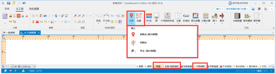
1. 对于对流, 地面/墙面辐射, 顶面辐射 编辑器的示意图 - 给水系统计算 编辑范围:

2. 对于给水系统计算 编辑器的示意图 - 排水系统计算 编辑范围:
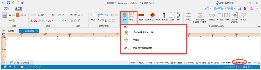
3. 对于排水系统计算 编辑器的示意图
- 对流, 地面/墙面辐射, 顶面辐射 编辑范围:
- 一个项目中创建的所有工作表类型: 示意图 列表位于视图管理窗口中。

4.位于视图管理器窗口中的工作表类型: 示意图


- 对流 、地面/墙面辐射 、顶面辐射 编辑器。
1. 示意图
- 对流 、地面/墙面辐射 、顶面辐射 编辑器。
所生成的工作表类型: 示意图 位于工作表清单下面的图纸列表中。

应用举例
检查连接
- 在执行创建 示意图 操作之前,必须执行检查连接 操作以检查项目连接的正确性,这是正确生成系统示意图的先决条件。项目文件可包含错误警告提示信息,但这些消息不能含有系统连接的错误。
- 检查连接 工具位于在主工具 选项卡,计算 工具栏中,也可以使用Shift+F2组合键来检查连接的正确性。
用于控制示意图自动生成的基本部件和功能的介绍
起始点
这是生成系统示意图的起点位置。必须为其指定一个唯一的符号。可以插入多个起始点 (供热供冷系统) ,每个都会生成一个单独的工作表类型: 示意图 ![]() 。如果删除了起点并再次执行创建 示意图 ,则工作表类型: 示意图 也将被删除。
起始点 (供热供冷系统) 可以放置在如下部件之上:
。如果删除了起点并再次执行创建 示意图 ,则工作表类型: 示意图 也将被删除。
起始点 (供热供冷系统) 可以放置在如下部件之上:
- 源
- 立管
- 管路
- 管线对.
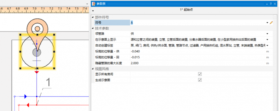
应在起始点 (供热供冷系统) 的参数表 窗口中,指定如下最重要参数:
- 领管路 - 从列表中选择一种管路类型 类型,该类型在生成示意图时具有优先权。在不对称安装的情况下(供水和回水的布置采用了不同的路径),此参数非常重要。所有接头(三通和四通)的标记和编号也将标注在领管路 上。该字段不适用于排水系统计算 范围内的起始点 。

4. 接点(三通)
范围可以减小:

- 隐藏管路的最大长度 - horizontal pipe-runs or series of pipe-runs of the system the length of which is less than that specified in the field are concealed in the 工作表类型: 示意图, if they constitute the first sections connected to the system. In the case of schematic views of a 管线对, both pipe-run types (供/回 or 热水/冷水) must fulfil the 隐藏管路的最大长度 criterion to be concealed. This effect does not apply to a pipe-run which is the last pipe in the system. The video shows the effect of changing the value in the filed on the generated schematic view:
- 立管确定示意图的方向 - 示意图上支管的敷设方向考虑了立管的视图指示器. The viewing direction is indicated by a triangle near the edge of the 立管, the location of which can be changed in the 2D编辑器 window after selecting the component. When in the 参数表 window of the 起始点 the 立管确定示意图的方向 box is checked, the 管路 components connected to the riser are drawn in accordance with the following rules:
- 管路 components located in the <0,180) area are displayed to the right of the riser.
- 管路 components located in the <180,360) area are displayed to the left of the riser.
Note:If the development of the 示意图 behind the risers is unsatisfactory, it is possible to uncheck this box and try to 创建 once again.
- 创建示意图 - Unchecking this box disables the generation of the schematic view during subsequent generations, e.g. new settings of the functions that control automatic generation of schematic view will not be applied. However, disabling this option does not affect the system components - refreshing is automatic, meaning that the number of system components in the model is always identical with the number of components in the schematic view. When 创建示意图 is disabled, the sheet selection list in the worksheet management window displays a padlock icon
 .
.
This is an excellent solution when working with multiple starting points. This function allows to "freeze" an already created 示意图 and generate subsequent ones without the fear of accidentally changes.
6. 创建示意图.
更多信息,见: Schematic view: how to eliminate warnings associated with an asymmetrical installation. - 在示意图上显示 - the scope of the generated schematic view can be controlled:
- 源和立管之间的装置 - generates the schematic view from the indicated point to risers, excluding the risers.
- 立管 - generates the schematic view from the indicated point to risers, including the risers.
- 立管后面的装置 - generates the schematic view from the indicated point beyond the risers to terminal units. If an installation includes stations, the schematic view is terminated at the station, if the installation includes manifolds, the schematic view is terminated at the manifold.
- 户用换热站后面的装置 - generates the schematic view from the indicated point to the station including the installation beyond the station (in this case 立管后面的装置 must be checked).
- 分集水器后面的装置 - generates the schematic view beyond the manifolds (in this case 立管后面的装置 must be checked)
- 自动创建标签 - select from the list the components for which labels are to be generated automatically in the schematic view.

7. 自动创建标签. - 显示所有房间 - when checked, the schematic view displays vertical lines representing room areas. Room labels can also be displayed, if in the 自动创建标签 field the 房间 is checked.
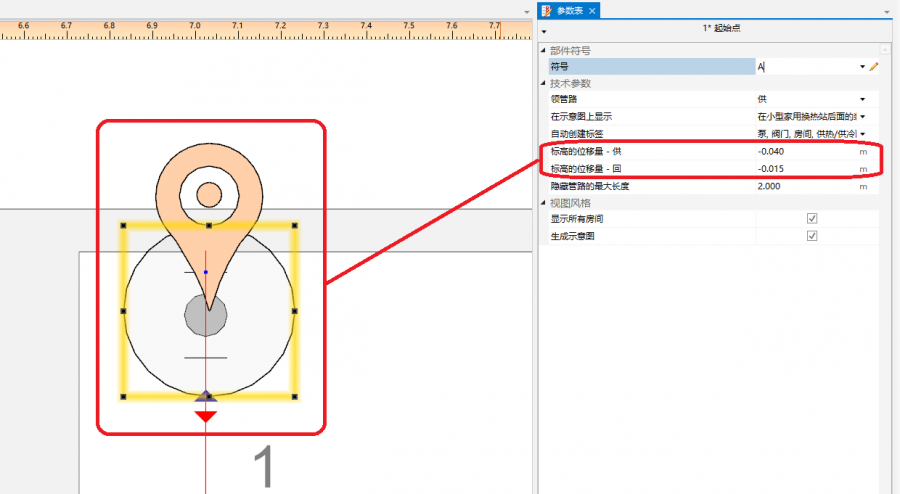
- 标高的位移量 - enables selecting the way of presenting in the schematic view of pipe-runs that are on the same level (elevation). Does not affect the elevation of the pipe-run in the model.
- Positive value - this value is added to the elevation of the supply pipe-run in the schematic view.
- Negative value - this value is subtracted from the elevation of the supply pipe-run in the schematic view.

8. 标高的位移量 in the schematic view of a water supply system.


This field is not available for the 起始点 component within the 排水系统计算 scope.
The 起始点 component also includes data that are associated with the design scope for which the component was inserted. More information is given further in the article:
- 起始点 for the 对流, 地面/墙面辐射, 顶面辐射 scope: Schematic view - Heating systems.
- 起始点 for the 给水系统计算 scope: Schematic view - Water supply systems.
起始点 (供热供冷系统)
这是所生成的系统安装示意图的起始点。必须给它命名一个唯一的符号。允许插入多个起始点 (供热供冷系统),并且每个起始点 (供热供冷系统) 都可生成一个工作表类型: 示意图 ![]()
起始点 (供热供冷系统) 可放在如下部件上:
- 源
- 立管
- 管线对
- 分/集水器
- 户用换热机组
3. 起始点 (供热供冷系统)

- 领管路
生成示意图时具有优先权的管道的标识。这对产生不对称安装(沿不同路径布置供回管道)时非常重要。所有接点(三通、四通)也将标记在领管路上。4. 接点(三通)
范围可以减小:- 源和立管之间的装置 - 生成从指示点到立管的示意图,不包括立管;
- 立管 - 生成从指示点到立管的示意图,包括立管;
- 立管后面的装置 - 生成从立管以外的指示点到末端设备的示意图。如果安装包括站,示意图终止于站;如果安装包括分集水器,示意图终止于分集水器。
- 户用换热站后面的装置 - 生成从指示点到站的示意图,包括站外的安装(必须勾选立管后面的装置 复选框)。
- 分集水器后面的装置 - 生成分集水器以外的示意图(必须勾选立管后面的装置 复选框)。
- 自动标签控制

5. 示意图 - 标签控制 - 标高的位移量
启用在示意图中显示同一标高(立面)上的管路。不影响模型中管路的标高。- 正值 - 该值将添加到示意图中的管道标高中。
- 负值 - 该值将从示意图中的管道标高中减去。
6. 标高的位移量 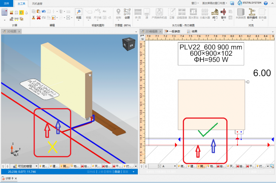
7. 标高的位移量 - 供回水管
- 显示所有房间
所标记的房间及其标签
8. 显示所有房间 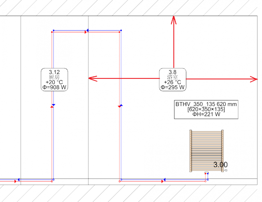
9. 显示所有房间 - 在示意图中标出的房间 - 创建示意图
不勾选此选项将在后续生成过程中禁用示意图的生成。对于自动示意图控制功能的新设置也将不予考虑。但是,禁用此选项不会影响安装系统部件。系统安装部件会自动刷新,即模型中安装部件的数量始终会与示意图中安装部件的数量相对应。如果禁用此选项,图纸选择列表中将显示一个挂锁图标。.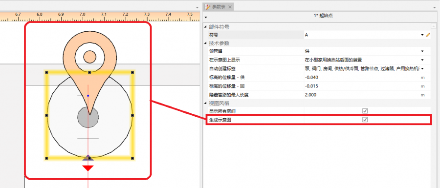
10. 创建示意图


控制点
开启控制在示意图上每个供回水管道生成的方向,并修改引导路径。它必须放在领管路上。控制点从其插入的交叉点开始改变示意图的路线。允许插入多个控制点,并且可以将其放置在一个工作表类型: 示意图 或一个工作表类型: 平面图 内。

- 方向
例如,指定将安装的一部分(例如:立管 )放在源 的右侧或者左侧。同样,也可以决定安装的一部分放在立管 的右边或者左边。本视频显示了如何在示意图中将两个立管移动到源的左侧的方法。
- 示意图中有断点
允许修改示意图的主路径。本视频显示了如何改变主路径,以便首先显示最不利路径。
终点
不生成终点 以外的安装部分的示意图。而这一部分安装的示意图由系统部件 表示。终点 必须分配有唯一的符号。
本视频显示了如何从示意图中移除立管。
不属于自动生成示意图的安装部分
- 带有顶面辐射板的安装。
- 带有墙面辐射板的安装。
这部分会自动使用一个系统部件 来终止。
手动编辑和配置
- 插入一独立部件。
下面的部件允许放在 工作表类型: 示意图 中:- 额外的标签(如:管路标签)。 所插入的标签的位置也可以改变 - 这些位置在示意图重新生成后保持不变。
- 阀门,
- 管路上的管件,
- 散热器配件。
其它信息
- 使用 InstalSystem 4 创建的项目文件,该文件包含加载到 InstalSystem 5 中的工作表类型: 示意图。
这样的工作表不会转换为 InstalSystem 5 的工作表类型: 示意图 ,当显示加载诊断信息时,会被删除。