屋面雨水排水系统的设计:修订间差异
| 第33行: | 第33行: | ||
项目包含有模板文件中设定的完整的缺省参数,建筑结构也已根据DWG布局做了详细说明。 | 项目包含有模板文件中设定的完整的缺省参数,建筑结构也已根据DWG布局做了详细说明。 | ||
== | ==设计步骤== | ||
=== | ===打开项目文件=== | ||
# | # 创建新项目时,请从列表中选择包含排水系统默认参数的模板。 | ||
# (or): upload an existing building structure file - minimum content is correct ordinates and slab thicknesses. | # (or): upload an existing building structure file - minimum content is correct ordinates and slab thicknesses. | ||
Verify and correct if necessary data that has a significant impact on the geometry of the drainage installation: | Verify and correct if necessary data that has a significant impact on the geometry of the drainage installation: | ||
2024年4月9日 (二) 15:50的版本
| 产品 | InstalSystem 5 |
| 文章类型 | DESIGNING LESSON |
| 版本的最新内容 | 2023-12-06 |
课程内容
本文介绍了重力式雨水排水装置的基本设计步骤。重力式雨水排水模块旨在设计和计算平屋顶或其他平坦区域(如露台)的排水管网。天沟不包括在内,因此倾斜屋顶不在项目范围内。计算基于 EN 12056-3 标准。
该模块在项目范围 中有一个单独的复选框。它在图形编辑器和模型视图中有自己的一般参数 数据、管道和计算选项、部件样式以及自己的编辑范围。启动计算的按钮以及检查连接 的按钮与生活排水模块共享。
模块和软件的配置
InstalSystem 5 需带有如下模块:
- 重力雨水系统
项目文件
本课程中使用的项目文件:Rainwater drainage installation in a multifamily building (example for the lesson).
初始状态
项目包含有模板文件中设定的完整的缺省参数,建筑结构也已根据DWG布局做了详细说明。
设计步骤
打开项目文件
- 创建新项目时,请从列表中选择包含排水系统默认参数的模板。
- (or): upload an existing building structure file - minimum content is correct ordinates and slab thicknesses.
Verify and correct if necessary data that has a significant impact on the geometry of the drainage installation:
- the 地面标高 or the 地形建模;
- the 厚度 of the slabs on particular storeys (ATTENTION! this may affect previously completed or planned designs of other installations in this file) - applies to terrace drainage;
- the 屋顶标高 and shape of the roof if the file contains the complete building structure.
Editing the general project data
Fill in the default data in the 一般参数 window:
- 项目范围 - determine project scope: 雨水排水系统计算.
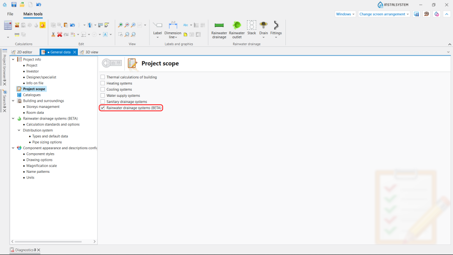
1. 项目范围. - 目录 – select and move necessary catalogues to the 项目可用的产品目录 table. To speed up the selection, the filters can be used. 更多信息,见: Using catalogues and catalogues data in the project.
- 计算标准和选项 – verify and correct if necessary:
- 降水强度,
- 坡度和充满度.
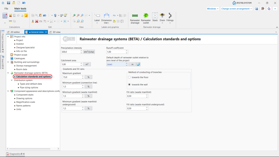
2. 计算标准和选项.
- 雨水排水系统计算 / 水力分配系统 / 默认类型和参数 – append default types:
- 默认的管材类型: 雨水排水系统,
- 管路连接的默认方式.
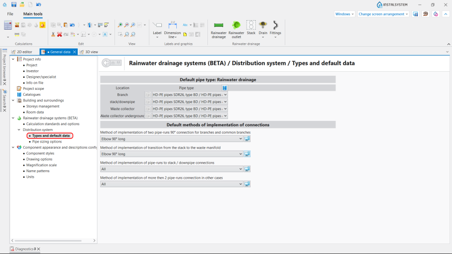
3. 默认类型和参数.
- Verify and correct if necessary settings on the tab 管材规格计算选型.
- 楼层管理 – verify and correct if necessary:
- 排水立管转成排水横管的拐点 - 指定排水立管转成排水横管的拐点与上方楼板或下方楼板的位置关系或距离(看示意图),以便在本楼层上绘制排水横管/横干管。
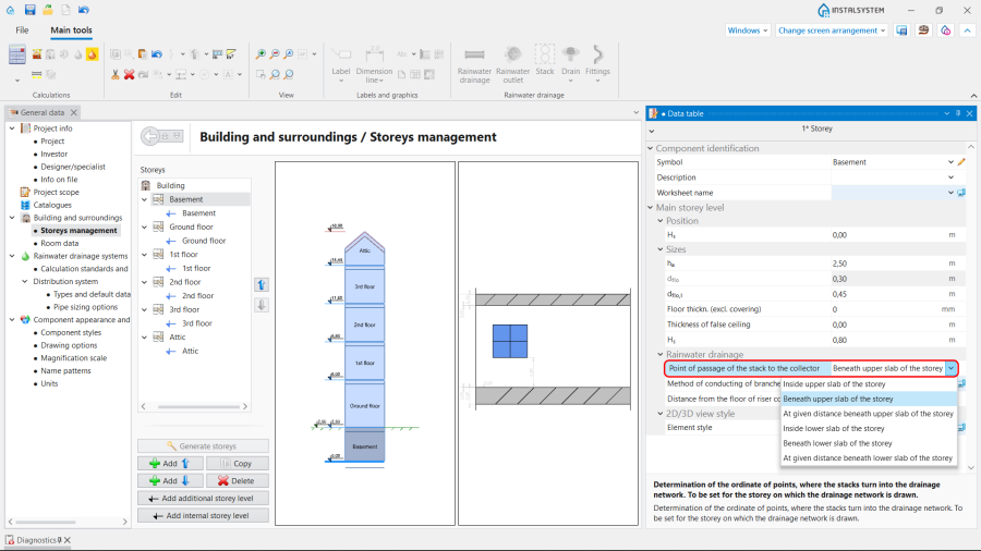
4. 排水立管转成排水横管的拐点. - 排水横支管在立管上的连接点与地面完成面的距离 - 对于所选楼层,排水横支管在立管上的连接点与地面完成面的默认距离值。对于多个连接到立管的每个排水横支管,均可在其参数表中更改此值。
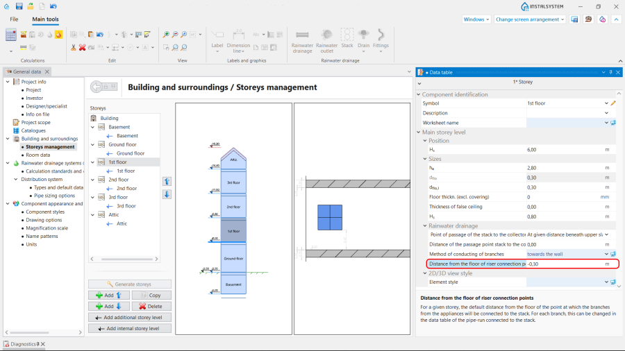
5. 排水横支管在立管上的连接点与地面完成面的距离.
- 排水立管转成排水横管的拐点 - 指定排水立管转成排水横管的拐点与上方楼板或下方楼板的位置关系或距离(看示意图),以便在本楼层上绘制排水横管/横干管。
- If the layout is the same on each floor, copy repetitive parts of the installation to other storeys using 将本层选中部件复制到上一层 or 将选定的部件复制到多个楼层 function.


Editing the installation and its data
Carry out inserting and graphic editing operations using the 捕捉 and 定向线 modes.
- Select editing scope 雨水排水;
- Insert the 地漏 elements: 屋面雨水斗 and 地漏, taking into account the building construction. Divide the catchment into parts according to the roof slopes;
- Specify the 汇水面积 for each using the 测量面积 function.
- Insert the 立管 elements and enter its data in the 参数表 window:
- In the 位置 section, declare the range of storeys of the 立管.
- Choose the 立管顶端的部件;
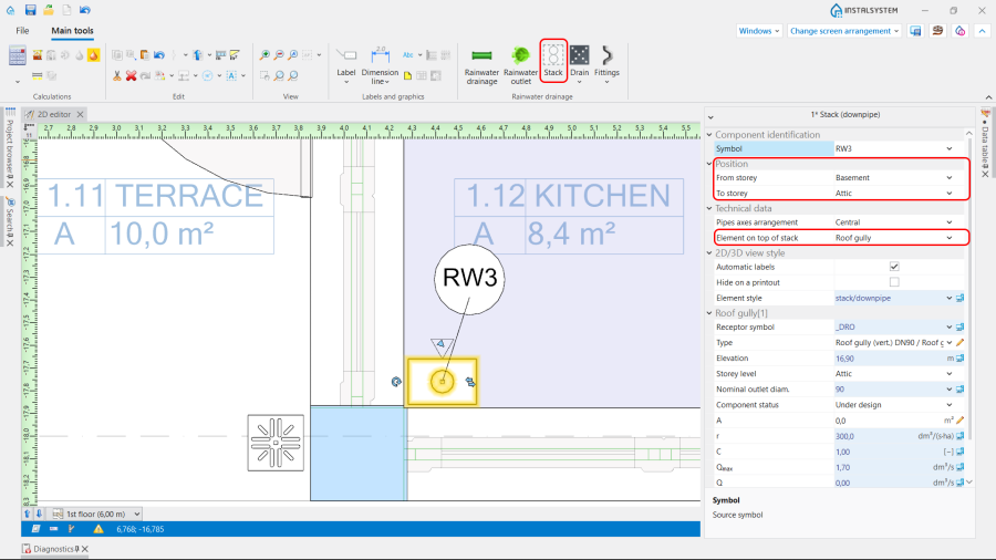
6. 立管 data.
- For the 屋面雨水斗 check and correct if necessary its 类型 and insert the value of the 汇水面积;
- For the case when the 连接至上方的立管 is chosen declare the point 所连接的立管符号 and set the 立管上方的拐点至天花板的距离.
- Insert the 雨水排出口 and verify its position in the model. ATTENTION! In one rainwater drainage installation can be only one 雨水排出口 element. But there can be several installations in one project.
- Connect the 立管 with the 地漏 elements using the 雨水排水系统 pipe-runs. If the 地漏 should be connected on an elevation different than the default, change 指定与立管连接位置的确定方式 to 用户指定, then set manually the required value of 立管连接点至地面的距离.
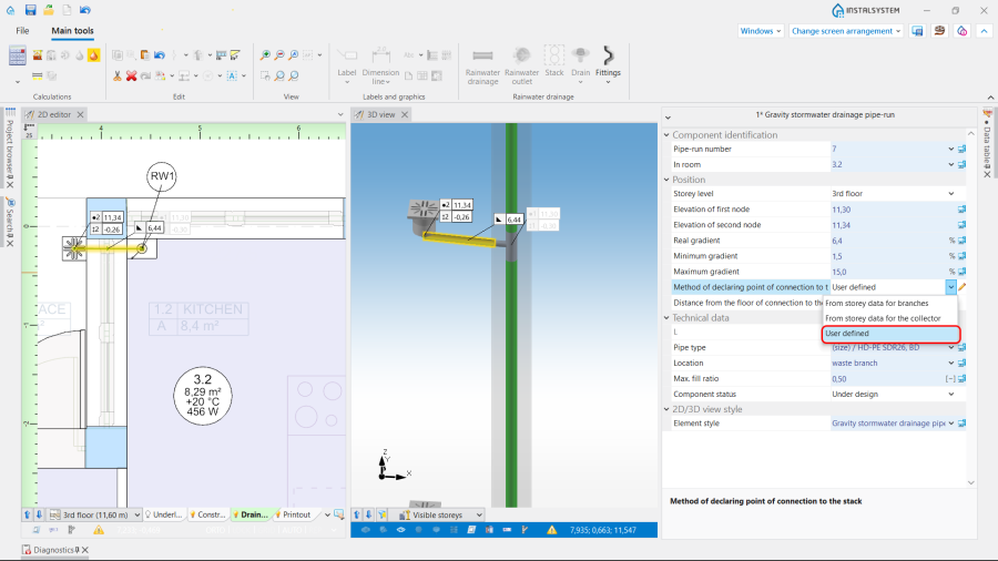
7. 指定与立管连接位置的确定方式. - Connect 雨水排出口 with the 立管 elements on the lowest storey to form the sewer collector network. This network is configured with consideration of the value of 排水立管转成排水横管的拐点 set in the 一般参数 window.
- (Optional) If needed, change the way of realizing chosen pipe-run's nodes to other than the default, set in general data. It is possible in the 参数表 window for the 管路节点 element.
- Insert necessary 管件 in the 2D编辑器 or on the 3D视图:过桥弯 and 沉积物收集器.
Choose the 类型 from available catalogues and, if necessary, adjust the 旋转角度.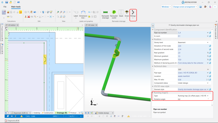
8. Insert 管件.


Verifying the correctness of the installation structure.
- Verify the correctness of the connections of the installation components using the 检查连接 function (Shortcut: Shift + F2);
- Verify the correctness of the installation structure using the 3D视图;
- Adjust the layout of the pipe-runs according to external factors, e.g. passages through walls, overlaps with other installations.
Running the calculations
- Start the calculation of the 排水系统计算 by clicking
 in the 计算 section of the toolbar;
 - Сheck messages the 诊断 window. First of all, eliminate 错误;
- Verify and adjust if necessary the layout of the installation: gradients, collisions, overlapping junctions, etc.

After the calculations, the vertical passage of the installation can be corrected by:
- imposing proper values in the 参数表 window for the 重力雨水排水管路 element in the following fields: 实际坡度, 第一个节点标高, 第二个节点标高,
- dividing the chosen pipe-runs into parts and modifying their data.
It is recommended to implement such changes gradually and to observe their influence upon the system, as the change in one node after calculations may have a significant impact on positioning of its greater part.
Note: Defining the vertical passage of pipe-runs, the program does not exceed the value imposed in the 最大坡度 field in the 一般参数 window in the 计算标准和选项 tab. This value is also automatically propagated to data of all pipe-runs. In case a difference of ordinates between the end of the calculated pipe-run and another pipe-run or a sewage outlet occurs, an additional vertical pipe-run is generated. To avoid it, allow for a greater gradient, by augmenting individually for each pipe-run a new value in the 最大坡度 field of the 参数表 and then recalculating the project.
Verification of results
- After calculations, the system layout should be verified visually by means of the 3D视图;
- If the calculations end with at least one error, the layout may be unreliable;
- The sized diameters of the pipe-runs and fittings can be verified directly in the drawings.
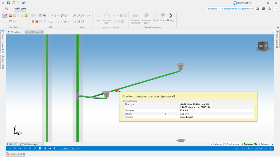
9. Visual verification in the 3D视图 window. - If a catalogue with visualisation of fittings (like tees, bends etc.) is used in the project, it can helpful in assessing the correctness of fittings selection and sizing for pipe-run nodes (junctions). To do so, node visualisation should be turned on in the 一般参数 window, on the 出图选项 tab, or using the icon of the 安装部件的可见性 directly in the 3D视图.
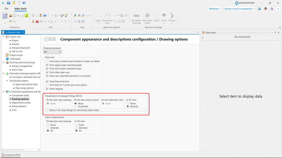
10. 排水系统管件的可视化.
Note: By default, only the nodes with correctly selected fittings, for which there are no warnings in the 诊断 window, are visualised. - Other forms of presentation of calculation results are: component labels and tables of results 更多信息,见: Presentation of the calculations result.
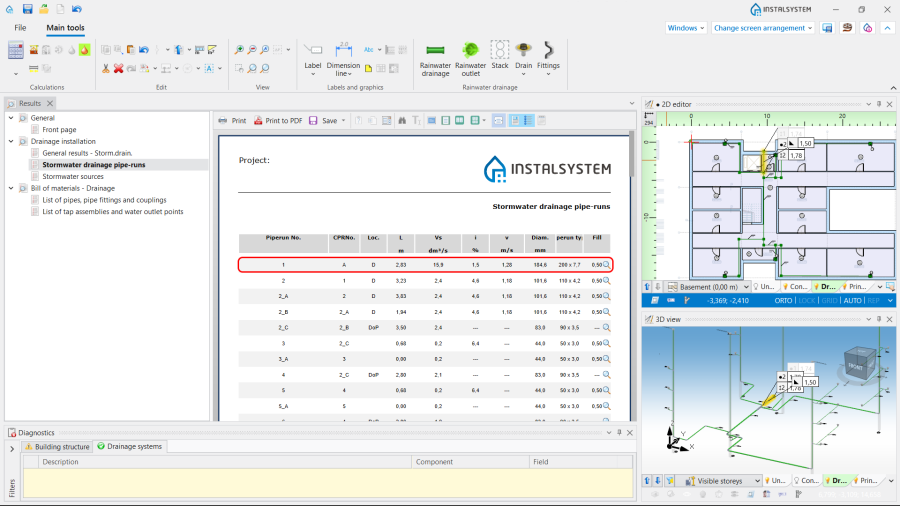
11. 管材、管件和接头清单.


Preparing drawings for export/printing
- To have the results for pipe-runs and installation nodes included in the printout of a drawing, appropriate labels must be inserted 更多信息,见: Preparation of drawings for export / printing.
- Completed drawings can be printed and/or exported 更多信息,见: Export / print results and drawings.